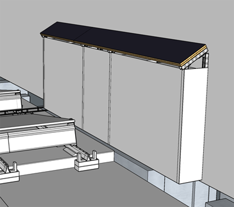
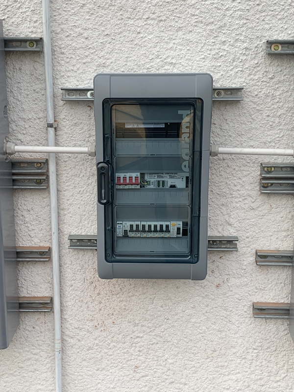
I previously showed my design for a solar sub panel, that will be mounted on the roof between the batteries.
This will be fed by a 2 core 16mm2 SWA cable and a separate 10mm2 earth conductor.
The distribution board is in the cupboard under the stairs in my entrance hallway, which is directly below where the solar sub panel will be mounted outside.
I had 2 choices:
- Bring the cable around the front of the house and then in under the floor of the shower room (alongside my EV charger supply cable)
- Come down through the roof beside a soil pipe and then under a corner of the kitchen floor.
I went for option 2 as it was less visible from the outside of the house, involved less actual cable and I already had a pipe installed in the roof for 10GB networking cable installed as part of my EDPM flat roof install.
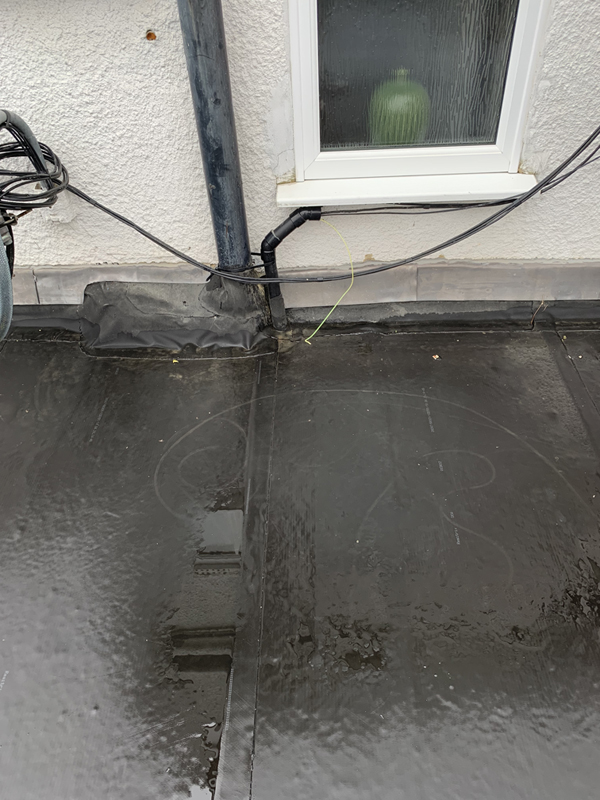
The Soil pipe is boxed in and as such I had to cut an opening at the top and bottom in order to be able to pull the cables, I also had to drill a hole in the wall at a downwards angle to go under the kitchen floor.
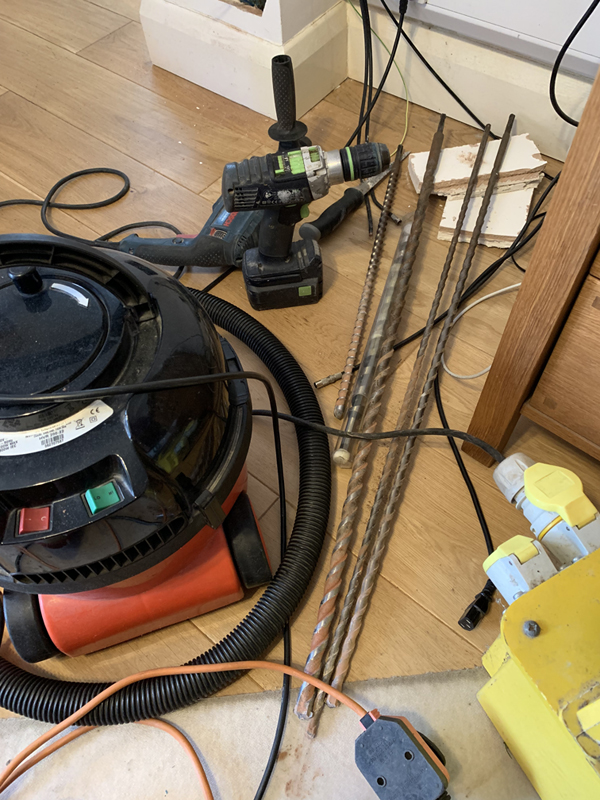


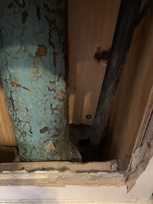
It was not easy or straight forwards, and not exactly helped by the amount of rubble that had been left by the builders under the floor from when the house was actually built.
I didn’t quite order a long enough piece of cable so I decided to fit an outside isolator as a ‘junction box’.
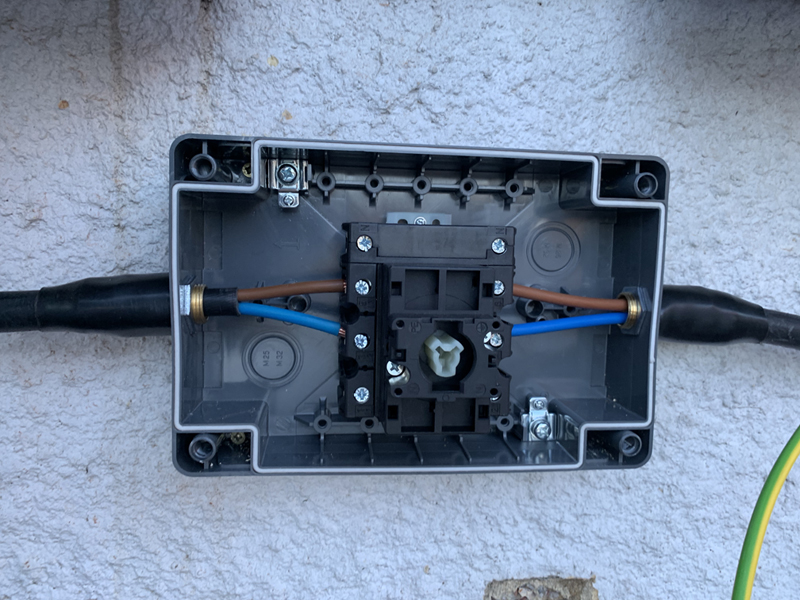 This also meant that I could have an RCD as the main ‘switch’ in the solar sub panel.
The batteries are connected to the sub panel via 22mm PVC conduit and 6mm2 individual cables, each pair of batteries has its own isolator in the sub panel that then connects to a 40A RCBO.
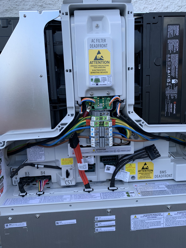
The batteries also have a data cable that runs to the Enphase Communications Kit 2.
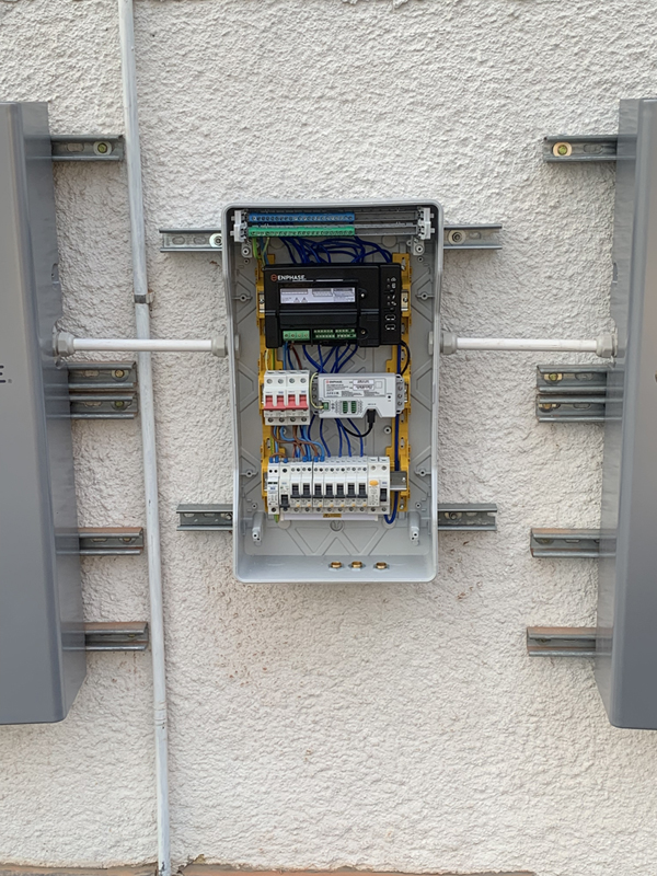
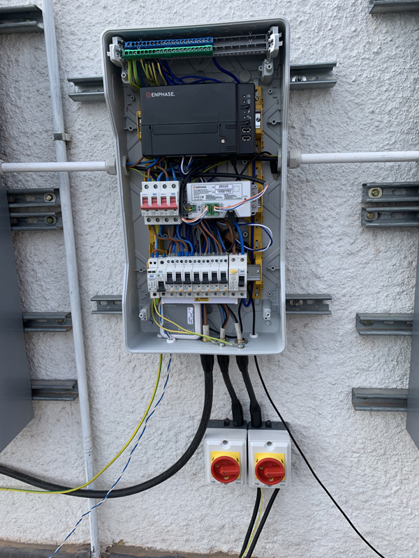
The various arrays connect to the sub panel via isolators and 4 core 6mm2 SWA, the right one is for the Office and Garage arrays, the left one will be for the East and West arrays.
Each feeds a pair of 20A RCBOs, one per array
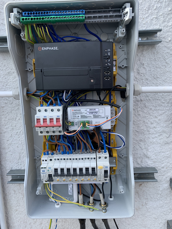
There is also a network cable for the Enphase IQ Gateway Metered, and the blue/white wires are from the CT clamp attached to the incoming supply by the DNO meter.
The production CT clamp is hidden behind the RCBOs.
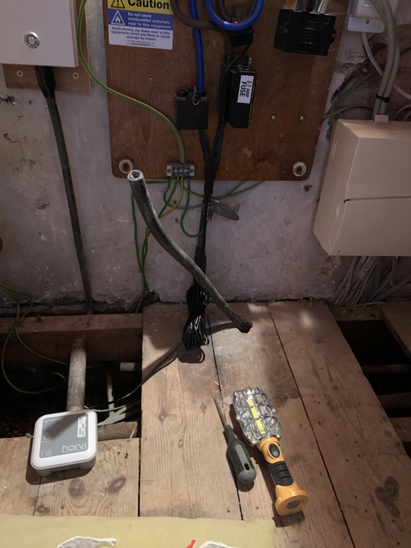
I have also moved the Myenergi Harvi from the cupboard under the stairs after running a dedicated network cable and CT clamp to the MyEnergi Zappi EV charger and then use it with CT clamps connected across both the solar production and Battery live cables (there is a third CT clamp input I can use at some future point if required).
I intend to build a roof/screen to help protect the batteries and sub panel from the elements which will be made from some more Unistrut elements and some balcony screening material: