I decided to simply bite the bullet and make all of the carbon tubes the same length, so I set up an end stop on my milling machine and held the shortest and one other tube in the milling vice, whilst I cut the longer one down with my Dremel.
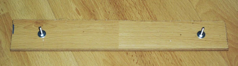
Next I made myself a quick jig to ensure that all the rods were exactly the same length once assembled.
This was simply a piece of left over laminate flooring with two 3mm holes drilled through it 228mm apart (it would have been 230mm if I had not needed to cut the tubes down) and then some long M3 screws secured through the holes to act as guides for the rod ends.
I then tried several different glues to attach the rod ends, there must be something wrong with my cheap Wilko brand super glue, because the only thing it seems capable of sticking these days is skin!
It had no interest in securing the grub screws to the carbon fibre tubes, in fact it was not even interested in drying out!
I eventually decided to use hot glue, this worked fine, although there was very little working time before it set.
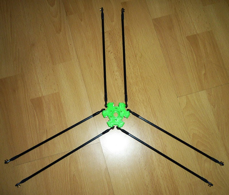
Here are three of the completed arms mounted on the jig.

Next, I attached one end of each of the arms to the effector to make a ‘spider’.
Then finally attached the spider to the sliders on the frame.
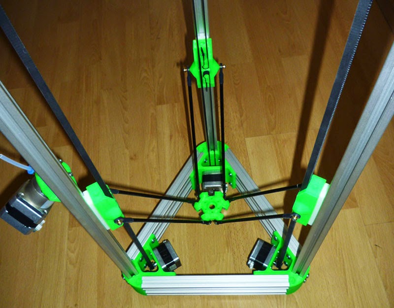
The level of lateral movement on the sliders has now vastly reduced.
At most I can move the effector 0.2mm in a circle without actually moving the sliders up or down, but since nothing will be attempting to push the effector out of position, it remains to be seen if this causes issues when printing.
I have been designing some mounts for the hall effect sensors in Google Sketchup, although I am not 100% convinced I like them yet.
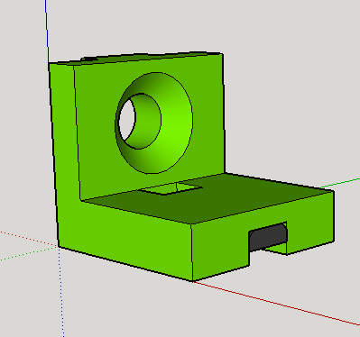
Here it is shown on the model in relation to the slider.
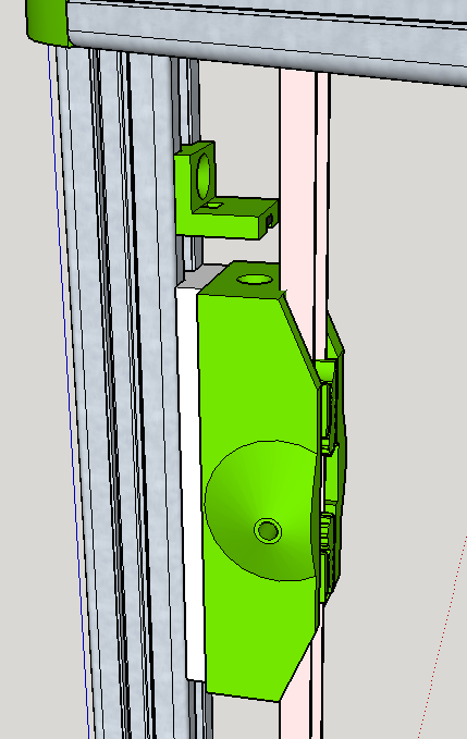
The wires from the hall effect sensor would come out in front of the screw and then be hidden within the 20×20 profile slot.
I would prefer the wires to come out at the back, but then I have no way of routing them past the T-nut, or past the T shaped base of the slider, that would be blocking the path of the wire.
Instead I will route the wire to the top of the frame and then back down the side of the 20×20 profile.
I likewise can’t use the centre of the profile for routing wires, as this has a foot screwed into it at the bottom, blocking the egress of the wires.
I may yet also have issues routing the wires past the tensioning screws at the top of the frame.