I was having yet another bash at persuading my breadboard based hardware to work with the I2C connected LCD display as mentioned in my Panelolu post.
I have been bashing my head against a wall with the Repetier firmware for months. Every time I had it use the LCD and uploaded the firmware, the whole board would hang just as it reached the initialisation of the LCD display.
I had tried with the built-in I2C library as well as several other Liquid Crystal libraries, none of which would work with Repetier once the LCD part was enabled.
I could manage to talk to the PCF8574P I2C chip and obtain the address with the Scanner program, I could also write my own code to talk to the LCD all of which seemed to work fine, yet no matter what I did the LCD would just not play ball with Repetier.
I decided to re-read a bunch of posts about the various Liquid Crystal I2C libraries along with checking the schematics used for each of them, re-check the pin configurations in Repetier and also how it was wired up on the board.
Eventually I discovered that I had the RS and RW pins backwards in uiconfig.h for Repetier and after one last compile and upload we had success and the LCD sprang into life. (kind of begs the question how it was working with the other pieces of software though).

This is my pin configuration for the LCD in uiconfig.h
/**
What display type do you use?
0 = No display
1 = LCD Display with 4 bit data bus
2 = LCD Display with 8 bit data bus (currently not implemented, fallback to 1)
3 = LCD Display with I2C connection, 4 bit mode
4 = Use the slower LiquiedCrystal library bundled with arduino.
IMPORTANT: You need to uncomment the LiquidCrystal include in Repetier.pde for it to work.
If you have Sanguino and want to use the library, you need to have Arduino 023 or older. (13.04.2012)
*/
#define UI_DISPLAY_TYPE 3
// This is line 2 of the status display at startup
#define UI_VERSION_STRING2 “Orig. Mendel”
/** Number of columns per row
Typical values are 16 and 20
*/
#define UI_COLS 16
/**
Rows of your display. 2 or 4
*/
#define UI_ROWS 2
/* What type of chip is used for I2C communication
0 : PCF8574 or PCF8574A or compatible chips.
1 : MCP23017
*/
#define UI_DISPLAY_I2C_CHIPTYPE 0
// 0x40 till 0x4e for PCF8574, 0x40 for the adafruid RGB shield, 0x40 – 0x4e for MCP23017
#define UI_DISPLAY_I2C_ADDRESS 0x40
// For MCP 23017 define which pins should be output
#define UI_DISPLAY_I2C_OUTPUT_PINS 65504
// Set the output mask that is or’d over the output data. This is needed to activate
// a backlight switched over the I2C.
// The adafruit RGB shields enables a light if the bit is not set. Bits 6-8 are used for backlight.
#define UI_DISPLAY_I2C_OUTPUT_START_MASK 0
// For MCP which inputs are with pullup. 31 = pins 0-4 for adafruid rgb shield buttons
#define UI_DISPLAY_I2C_PULLUP 31
/* How fast should the I2C clock go. The PCF8574 work only with the lowest setting 100000.
A MCP23017 can run also with 400000 Hz */
#define UI_I2C_CLOCKSPEED 100000L
/**
Define the pin
*/
#if UI_DISPLAY_TYPE==3 // I2C Pin configuration
#define UI_DISPLAY_RS_PIN _BV(4)
#define UI_DISPLAY_RW_PIN _BV(5)
#define UI_DISPLAY_ENABLE_PIN _BV(6)
#define UI_DISPLAY_D0_PIN _BV(0)
#define UI_DISPLAY_D1_PIN _BV(1)
#define UI_DISPLAY_D2_PIN _BV(2)
#define UI_DISPLAY_D3_PIN _BV(3)
#define UI_DISPLAY_D4_PIN _BV(0)
#define UI_DISPLAY_D5_PIN _BV(1)
#define UI_DISPLAY_D6_PIN _BV(2)
#define UI_DISPLAY_D7_PIN _BV(3)
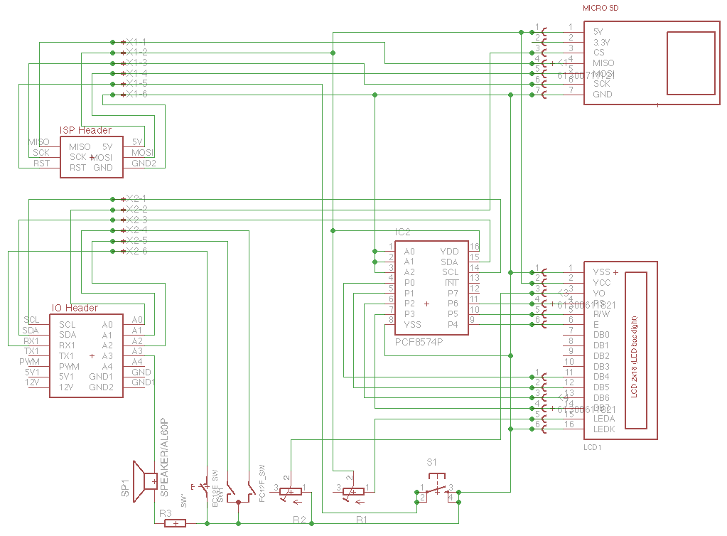
The _BV values are the P0-P7 pins from the PCF8574P chip – I only needed P0-P6, D0-D4 are for the low nibble, D5-D8 for the high nibble, you can connect in 8-bit mode if you have enough pins (D0-D7), or you can connect in 4-bit mode (D5-D7), you just pretend that both sets are connected to the same pins and both the low and high nibble data is transferred over these 4 pins.
As mentioned in my Firmware and Making Fumes post, I have 10 pins to play with (13 if you include MOSI, MISO and SCK) on the sanguinololu.
Now I have reduced my LCD pin requirement from 6 to 2, I have a few more to play with, which means I can use the buzzer again, and still have 3 pins spare.
| Physical Pin # | Pin Name | Sanguinololu Pin | Arduino Use | My Use |
|---|---|---|---|---|
| 7 | PB6 | D7 | MISO | SD card MISO |
| 6 | PB5 | D6 | MOSI | SD card MOSI |
| 8 | PB7 | D5 | SCK | SD card SCK |
| 40 | PA0 | A0/D31 | GP I/O | SD card CS |
| 9 | RST | RST | RST | Reset Button |
| 38 | PA2 | A2/D29 | GP I/O | Encoder 1 |
| 39 | PA1 | A1/D30 | GP I/O | Encoder 2 |
| 16 | PD2 | D10 | RX1 | Encoder C |
| 37 | PA3 | A3/D28 | GP I/O | Buzzer |
| 22 | PC0 | D16 | SCL | I2C LCD SCL |
| 23 | PC1 | D17 | SDA | I2C LCD SDA |
| 36 | PA4 | A4/D27 | GP I/O | Free |
| 5 | PB4 | D4 | PWM | Free |
| 17 | PD3 | D11 | TX1 | Free |
I have not compiled in the extra code for the rotary encoder or the buzzer yet, but things are looking good for using an ATmega644P rather than needing the more expensive ATmega1284P, as the compiled code is only 47,928 bytes. Previously with the Marlin firmware, after enabling the LCD code, I was beyond the 64Kb limit of the ATmega644P.
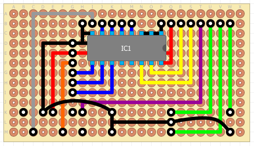
Here is a possible interface board for the panelolu.
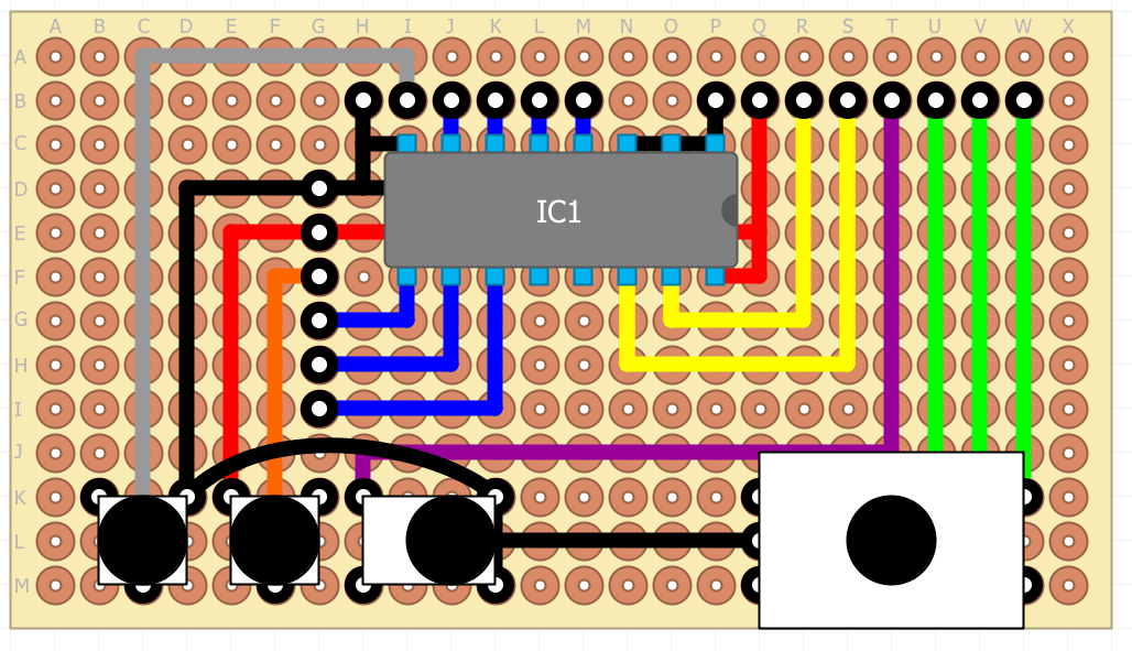
And without the components covering the connections.