I have been collecting parts for a while now and whilst I am still waiting on some, I thought I would get started.
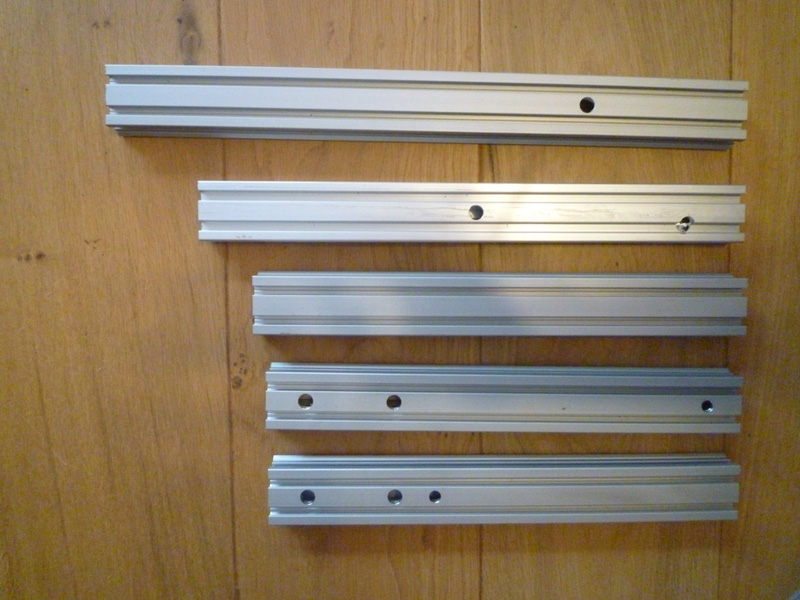
First off I needed to cut the Makerslide to length, the build calls for 3 x 330mm lengths and 1 x 430mm length along with 1 x 370mm length of 20x40mm profile.
I cut a 330mm length off either end of a 1m length of Makerslide and left the remaining piece at 340mm, this one will be used for the X axis.

Next I marked out the hole positions for the hidden wiring and started to drill them out, but after the first hole started going oval and I had no hope of drilling the offset hole, I decided to use a 10mm milling cutter on my Mini Mill instead.
For the 7.75mm holes, I just used an 8mm milling cutter. I tested with a spring and I believe it is still tight enough.
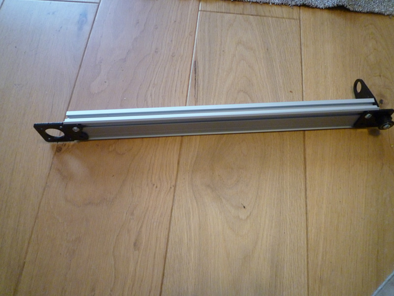
I tried lining up the holes on the Z axis uprights against the handle piece and noticed that they did not line up! I rechecked the drawing and where I had marked and drilled and all was correct, it appears that the handle was cut with the top 2 slots 5mm up from from where they should be.
Not a major issue, back to the milling machine and mill the hole up 5mm to form a slot.

Since I want to mount my power supply under the Y axis, I decided to mill a second offset 10mm hole in the 20×40 profile that would line up with the other Z axis upright as well as continue the middle hole all the way through.
I tapped two M5 threads in one end of the Y axis before attaching the foot, motor and pulley brackets.
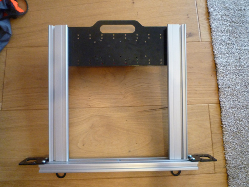
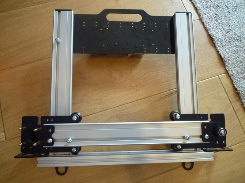
Here is a shot of the Z axis/frame with the handle, 2 motor mounts and 2 feet attached.
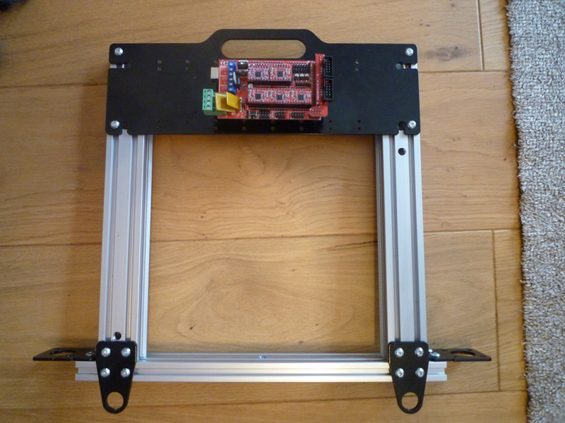
View from behind showing the ATmega2560 and Ramps 1.4 board attached.
I don’t have any angle brackets at present, so these will have to wait.
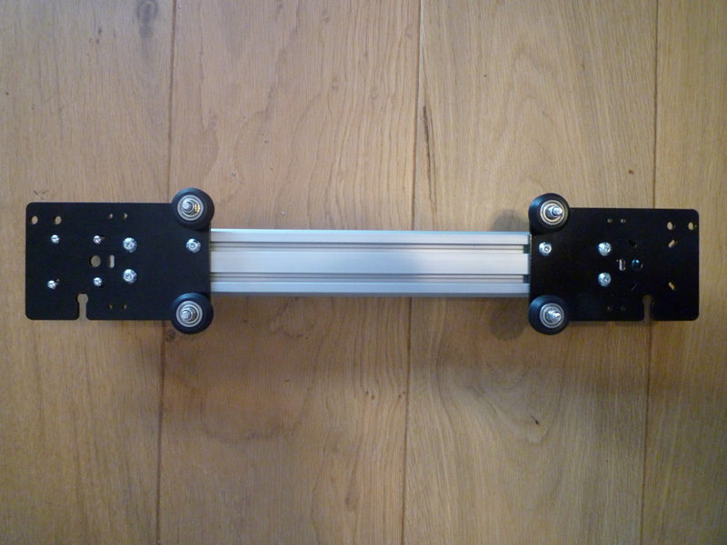
For the X axis I have attached 2 x V wheels to each gantry plate, I am still waiting on eccentric spacers, so I can’t attach all wheels yet.
I have also attached a pulley mount and the spare motor mount such that I don’t need to use 38-40mm spacers for the motor, I can use 20mm spacers instead which will be much stiffer.
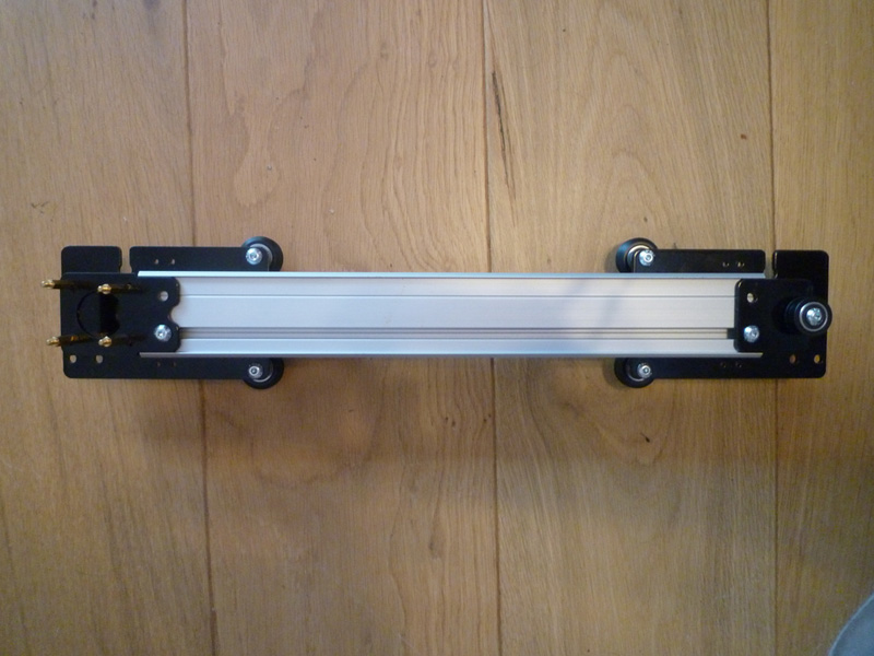
View from the rear of the X axis gantry.
I also installed some the end stops, these are made up from 1/4″ nylon spacers and M5 screws, although these may need to be changed for M4 grub screws if they interfere with the belts on the various axes.
Here you can see the X axis gantry installed on the Z axis, some of the end stops are also visible
As mentioned, I don’t have any angle brackets, so I can’t attach the Y axis at this moment in time.