I have been having issues with my printer for quite a while now – at some random point it will skip a step and cause the print to shift over to the left or right by about the width of the extruded filament.

This could happen several times during a tall print and result in a slightly wavy appearance to the outside of the printed part.
Not necessarily an issue for items where a perfect edge is not required, however a major issue if that perfect edge is required for lining up against some other item, or for a rod or similar to pass through a hole.
The skipped step is totally random and can occur after 1, 10 or 30 layers, and again randomly after that, sometimes continuing in the same direction, other times correcting the previous skipped step.
I am pretty sure it is not the steppers over heating, nor is it a function of an out of square printer as it is even random when repeating the same print – no 2 prints have the skips in the same place.
One thing that does seem consistent is that it seems to happen after a particularly noisy switch off of the relay controlling the heated bed.
This led me to think that it was possibly back EMF from the collapse of the relay circuit hitting the controller board and causing a skipped step – not enough to reset the board, but enough to cause problems.
I have tried printing with the heated bed switched off and the issue appears to go away, thereby lending credibility to the theory.
Unfortunately printing with the heated bed switched off on taller prints leads to the print being pulled off the bed.
I was already using a flyback diode, however, it is suggested here that there are better ways of reducing the back EMF by additionally using a resistor or a zener diode.
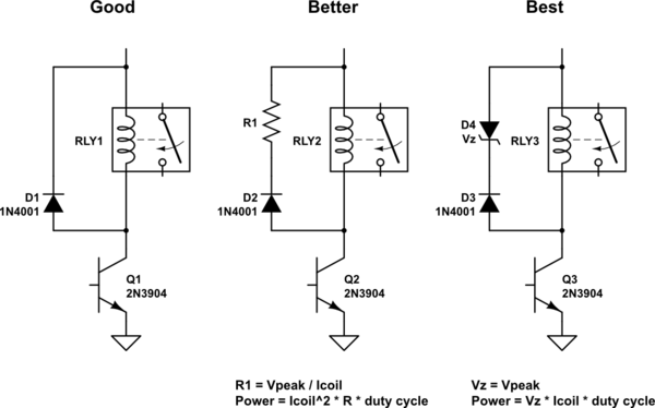
I found a suitable zener diode and updated my relay wiring, unfortunately this had no additional benefit.
So the conundrum remained – print with the heated bed switched on and have issues with prints over 10mm tall, or print with the heated bed switched off and have them pulled off the heated bed at about 12mm tall.
Neither option was really viable from my point of view, so I came up with a couple of alternatives:
- Use a frosted piece of acrylic as a bed
- Use a separate controller for the heated bed
- Use a separate controller and separate power supply for the heated bed.
The frosted acrylic method is what I intend to use on my delta printer, however if I ever want to print with ABS, I will need to fix the heated bed, so I started down the road of a separate controller.
At first I thought I would use something along the lines of this Thing, however I thought it was way to expensive and over complicated.

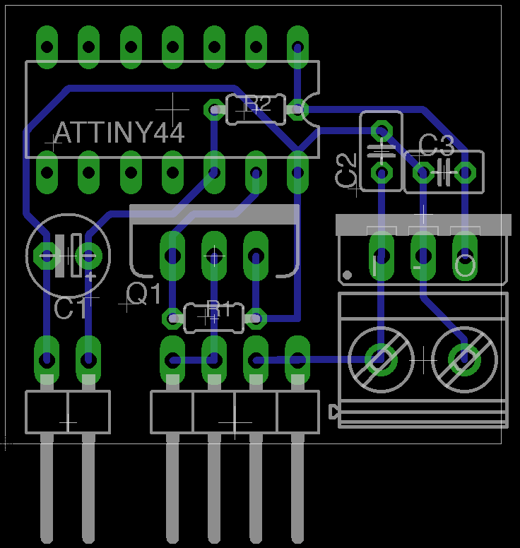
Most of the parts could be scaled back and I could use an ATtiny44 rather than a full blown Arduino Uno plus shield.
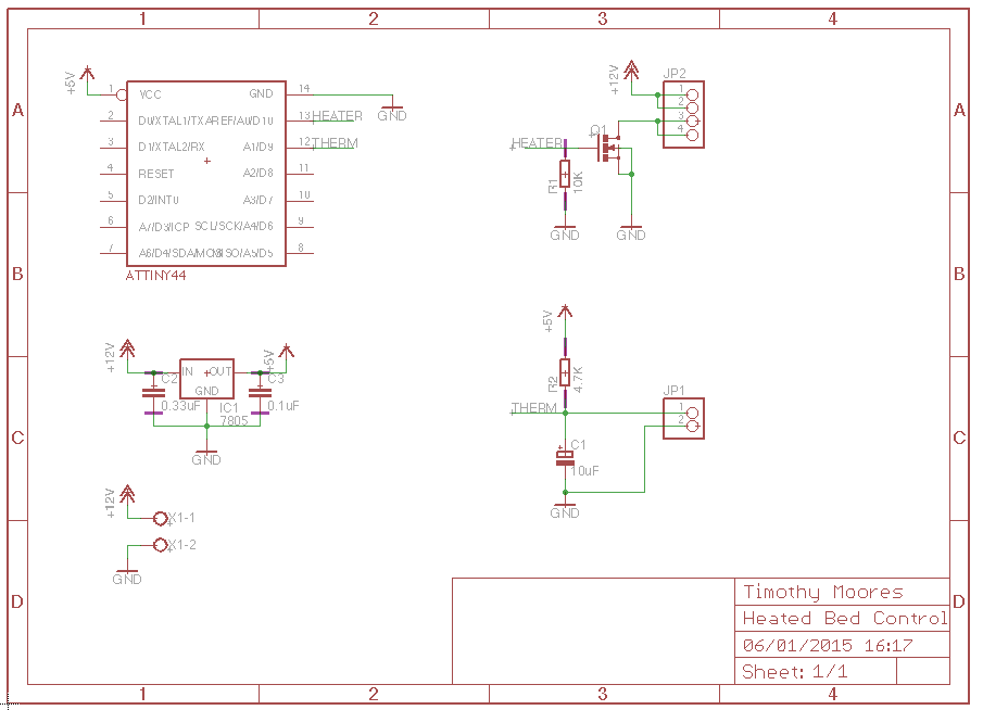
I designed a suitable schematic and board in Eagle and set about obtaining suitable snippets of code to write the control software.
After talking this through with a few different people, one suggested a 555 timer circuit to do it all in hardware, so I thought – hey why not give that a go.
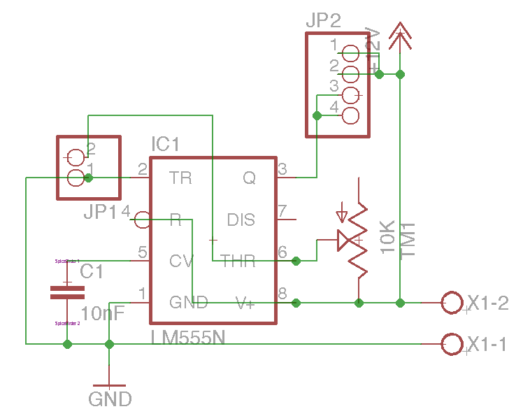
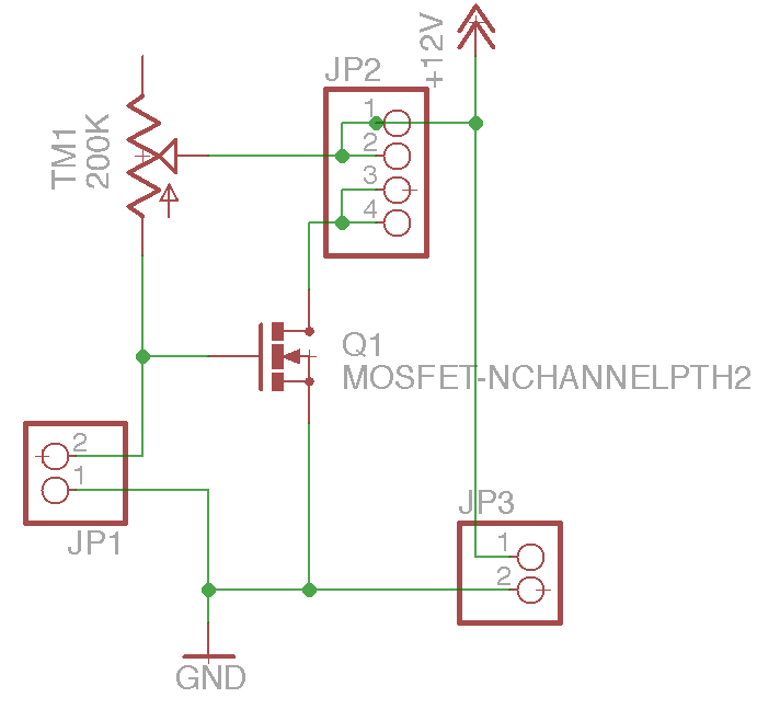
Ideally I would require a transistor or better yet a MOSFET to trigger the relay, at which point it occurred to me that I could actually do away with the 555 chip as well and simply use the thermistor and variable resistor as a voltage divider to trigger the MOSFET directly.
There are 2 variations of this circuit, one for heating and one for cooling depending on which item is closest to the supply voltage and which is closest to ground.
I wanted one for heating, so the thermistor goes at the top.
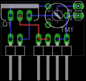
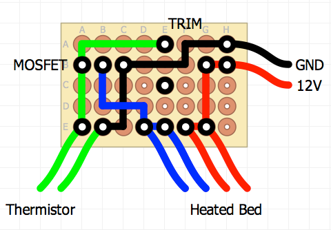
The same board shown on a small piece of perfboard.
Next one needs to select a suitable value for the variable resistor based on the trigger value of the MOSFET and the required temperature on the heated bed thermistor.
I am using a Semitec 104GT thermistor and the various temperature/resistance values can be found in the associated datasheet.
The various formulas for calculating R1, R2, Vin or Vout are all on the Wikipedia page, I simply plugged them into a spreadsheet along with a lookup table for the thermistor temperature/resistance values to work out values where the MOSFET would come on at room temperature and switch off at about 60C.
Using a supply voltage (Vin) of 12V, trigger voltage (Vout) of 2V which is pretty standard for a MOSFET and thermistor resistance (R1) of 22.51K Ohms at 60C, gave a variable resistor setting (R2) of 112.55K Ohms, this in turn would have a Vout of 2.75V at 50C and 1.44V at 70C, so about the right range.
In practice whilst the MOSFET triggers at 2V, the gate is not really open or close until around 3V (see the datasheet) and as such the bed was still too cold as it was shutting off at about 40-45C.
I adjusted the calculations using this new 3V Vout value and came up with a new resistor value of 67.53K Ohms at 60C, which gave Vout of 3.98V at 50C and 2.23V at 70C.
This had the desired effect of reaching somewhere near the correct temperature as a side comment the relay turns itself on and off in a much more gentle manner as the voltage change is much slower than the previous strict on/off method.
As a result of the lower resistor values for R2, I could have used a 100K Ohm variable resistor as opposed to the 200K Ohm one I thought I needed initially based on an R2 value of 112K.
Should I decide to print with ABS and set the bed to 110C, the resistor would need adjusting to 12.24K Ohms, the Vout at 100C would then be 3.75V and at 120C would be 2.39V.
In total just a couple of components and half a small perf board for a total of just over £1.50 including all of the connectors (which could all have been left as pin headers to save about £0.50).
The board is currently powered directly from the 12V power supply, so the heated bed is active whenever the printer is powered up, I may yet connect it through its own switch so it can be turned on and off independently.
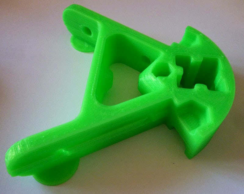
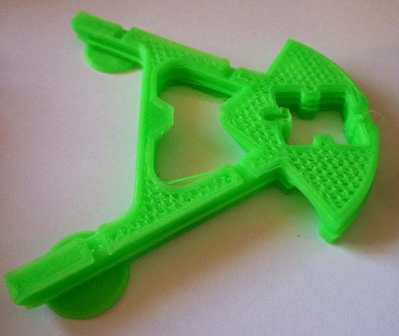
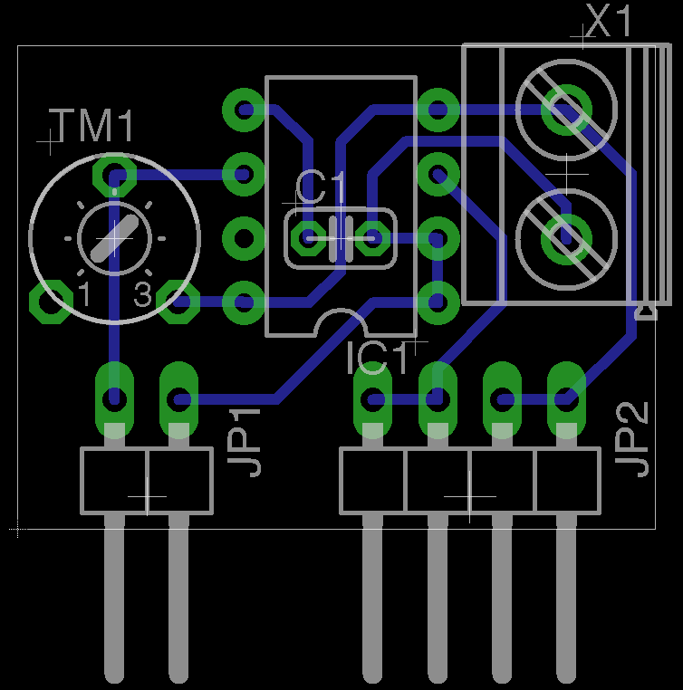
Here are the front
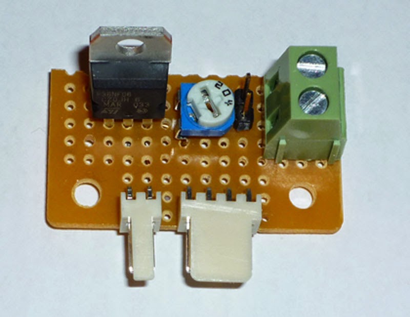
and rear views of the completed board
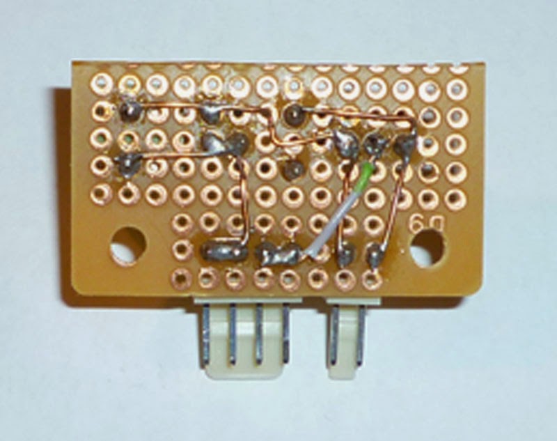
The copper wire is 4 sections cut from a single core of CAT5 network cable, only the last of which still has its insulation in place.
I have both pin header and screw terminal connections for power, the thermistor and heated bed connections are wired exactly the same as for connecting to the Sanguinololu.
My next print came out perfectly with no skipped steps whatsoever, and was not pulled from the bed.