Well after loads of trial and error and lots of searching on the web, I am finally able to talk to the ATmega644p chip on my breadboard via a bluetooth connection.
There were 2 issues:
First, I have no RST pin on my bluetooth module, so I had to find a way of generating one.
This involved attaching a wire to the place where the “status” pin would be connected (basically looped through from the status LED, that actually connects to pin 32 of the HC-05 board that is soldered onto the module) then connecting this via a 1uF capacitor to the reset pin of the ATmega644p.
Now when I power up the board, initially both the ATmega644p and the BT module flash until a connection is established.
Once a connection (like from Printrun) is made, the capacitor delays this connection to the reset pin allowing the chip to reset one last time and then keep that pin held high and allowing programming to happen.
Second, I had the RX and TX pins connected backwards, once this was sorted, Printrun was able to see the “printer” as online. It would seem that these pins are connected differently to my CP2102 programmer, despite being labelled the same.
Still I have never known any harm come from connecting these the wrong way round, and often found this to be a suck it and see exercise to locate the correct orientation of the 2 pins – TX-TX and RX-RX never actually achieves anything – 2 sides attempting to talk on one pin but both listening on the other.

Further tests have shown that I don’t actually need the status pin connected for Printrun to talk to the chip, if I had sorted problem 2 first, I would have noticed this sooner, though it may still be required for wireless re-programming should I feel the need to do this from avrdude or Arduino.
I have been having a closer look at the Sanguinololu schematic:
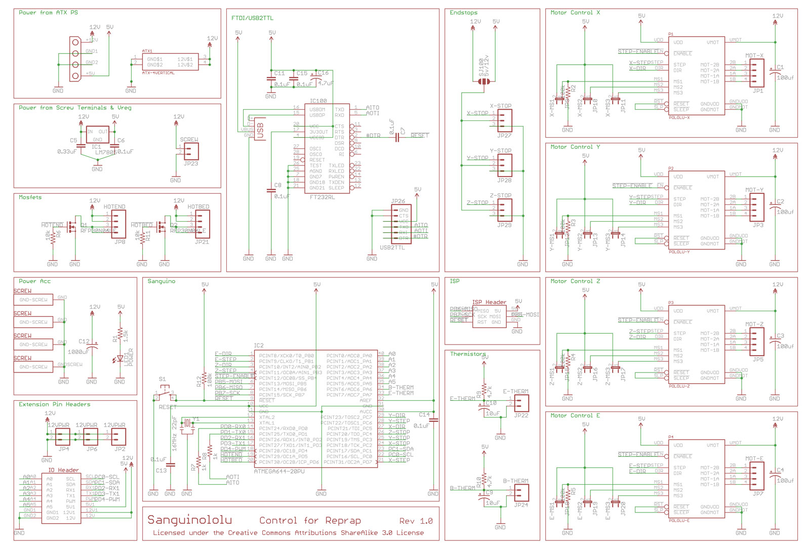
I am wondering if one can get away without needing to install the FTDI chip at all, especially if you have access to an external serial programmer like the CP2102. all the pins for the USB2TTL connector loop through to the relevant pins on the ATmega644p chip, and all of the pins required for flashing the bootloader are available via the 6 pin ISP header (also used by the SD board).
This would mean a potential saving of 5 components:
IC100 – FTDI chip
PS1/PS2 – USB connector
C8, C11 & C15 – 0.1uF Capacitors
C16 – 4.7uF Capacitor
The FTDI chip and USB connector are the most expensive components on the board after the Stepper drivers and the ATmega644p chip, a programmer like the CP2102 can be had on eBay for as little as £1.83, the FTDI chip alone costs more than that, and without it, there is no SMD soldering required at all.
I have since seen this confirmed by some of the postings on the forums, though it is far from obvious on the Wiki, or the github home of this product.
I have ordered a couple of microSD card adapters:
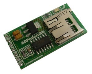
| Sanguinololu | ADPmicroSD |
|---|---|
| 5V | 5V |
| GND | GND |
| MOSI | MO |
| MISO | MI |
| SCK | SCK |
| A0 | CS |