My new E3D hot end clone turned up the other day for my Mini Kossel, this cost £7.49 ($11.60) with free P&P from ebay seller digital_store_2014.
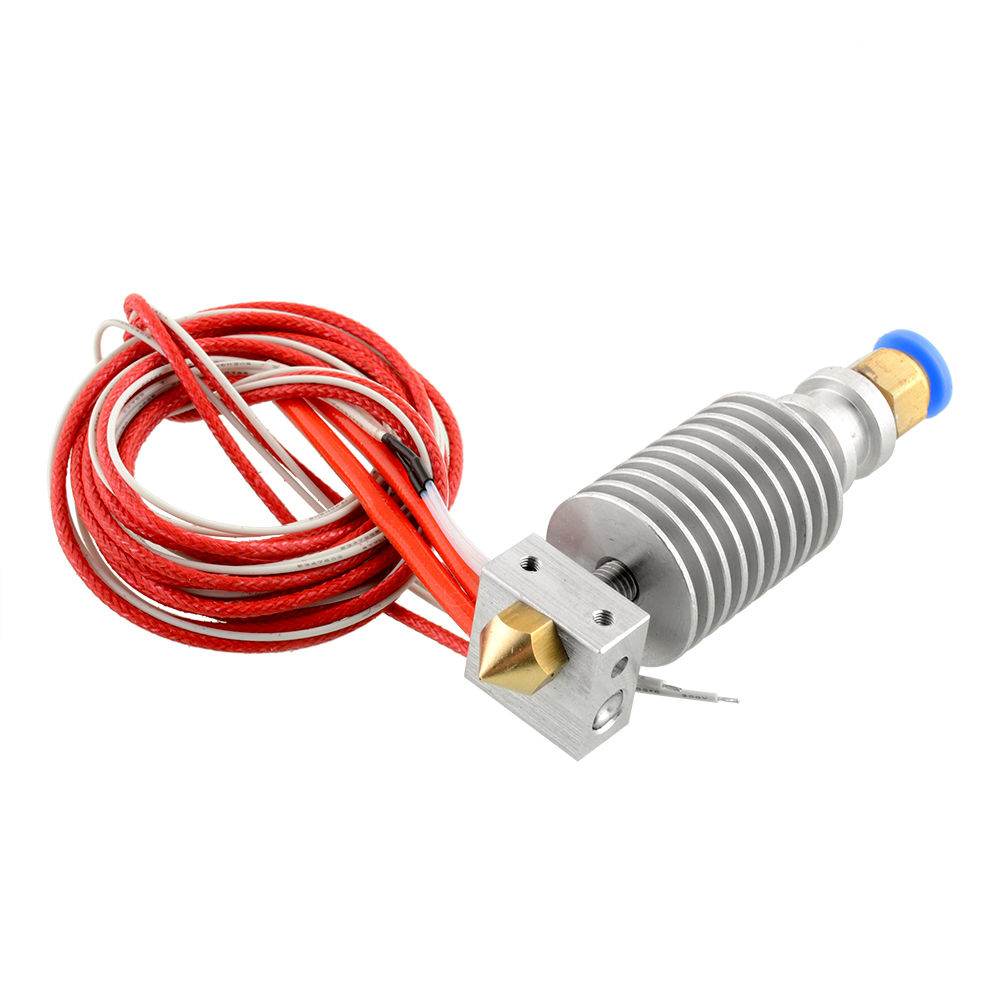
I will replace the thermistor with a ATC Semitec 104GT-2 so that it is a known quantity, rather than the complete unknown that came with the hot end.
Based on the issues I had in the early days with my Prusa I3 printer and having to manually turn a spool of filament, I decided to get ahead of the game this time and print a spool holder.
I particularly like the look of this minimalist spool mount and guide on Thingiverse

As there are really only 2 different items to print, I need 3 of one of them and they are all pretty small, I decided to print them all at once.
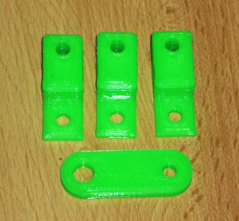
In total this used 5767mm of filament for a cost of £0.216.
To make them up required 6 x 625 bearings, 5 x M5x20mm screws, 3 x M5x10mm screws, 1 x M5x30mm screw, 6 x M5 nuts, 3 x M5 T Nuts and 11 x M5 washers.
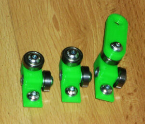
The 625 bearings were £1.61 ($2.50) for 10 from ebay seller warm_tech, the screws, nuts and washers were all from Orbital fasteners, and the T-nuts were $7.50 (£4.85) for 100 from robotdigg.
This makes the total cost (6 x 0.161) + (5 x 0.0484) + (3 x 0.0394) + 0.0697 + (6 x 0.0041) + (3 x 0.0485) + (11 x 0.0041) = £1.61 ($2.50).
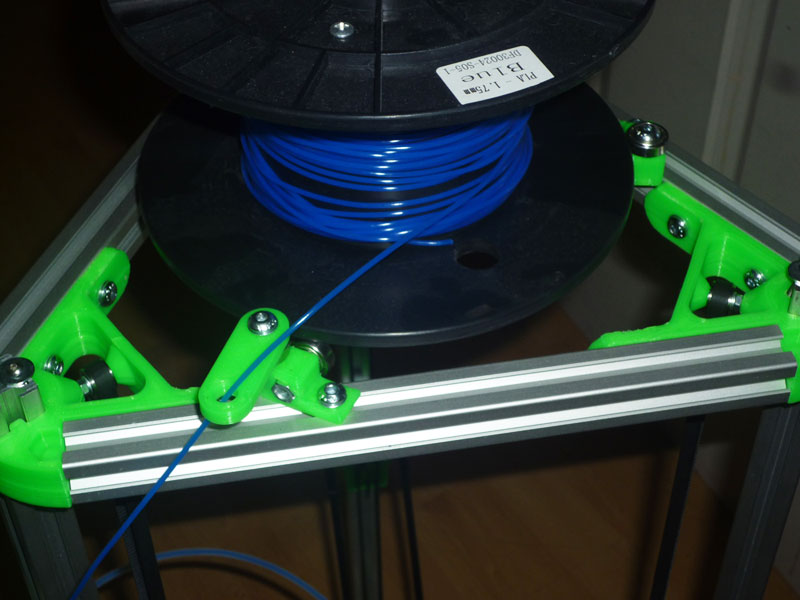
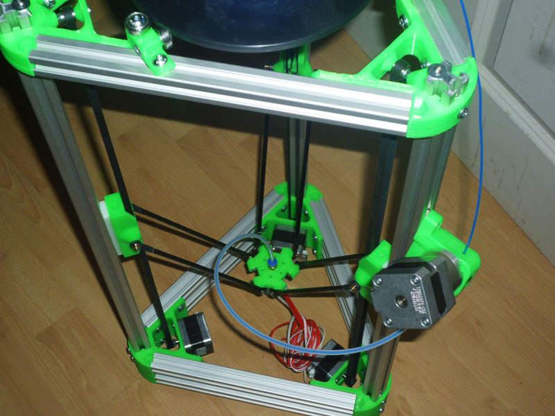
These were then installed on the top of the frame and adjusted to fit one of my spools of filament.
I then relocated the extruder stepper motor and fitted the hot end and a length of 4mm OD, 2mm ID PTFE tubing between the push fit connector on the extruder and the one on the hot end.
I am still deciding on how thick an acrylic printing surface I want to use, I will either settle on 10mm, or 5mm and a 2mm aluminium sheet underneath it for additional rigidity.
5mm will be cheaper at half the price, but also half the rigidity.
I have designed some end stops for use with my hall effect sensors and magnets in Sketchup.
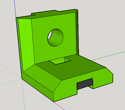
For some reason Slicer did not like the countersinks I had put in the holes, it was convinced that there was a hole in the solid, so I decided to print them without and manually countersink them afterwards.
The slot for the hall effect sensor curves upwards towards the rear to help the pins exit the hole.
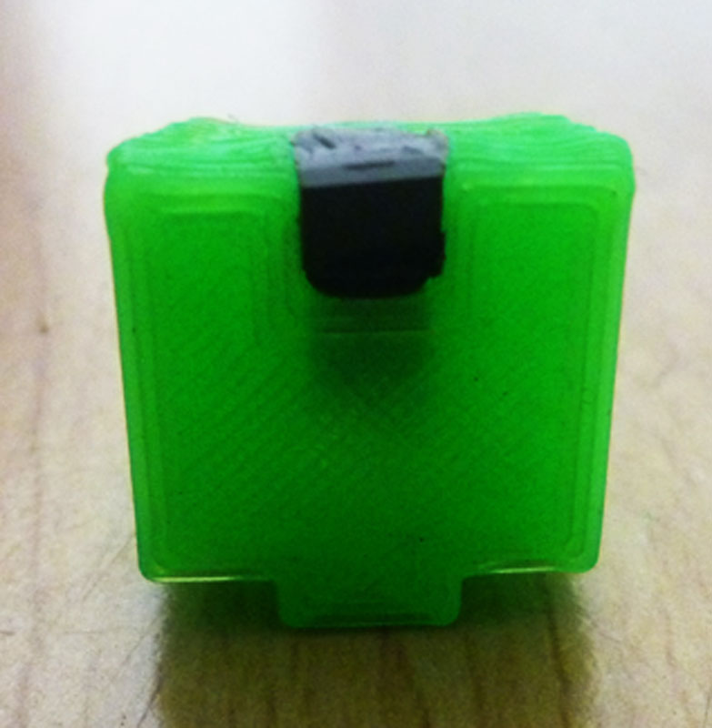
Here are the end stops hot off the printer.
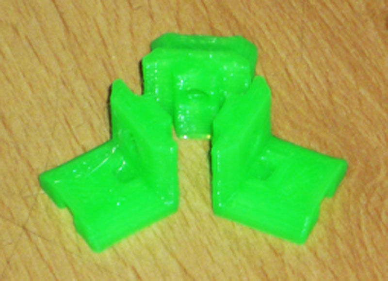
The 3 end stops used 1572mm of filament for a total cost of £0.06.
Here is one with the hall effect sensor installed and held in place with some blue tac.
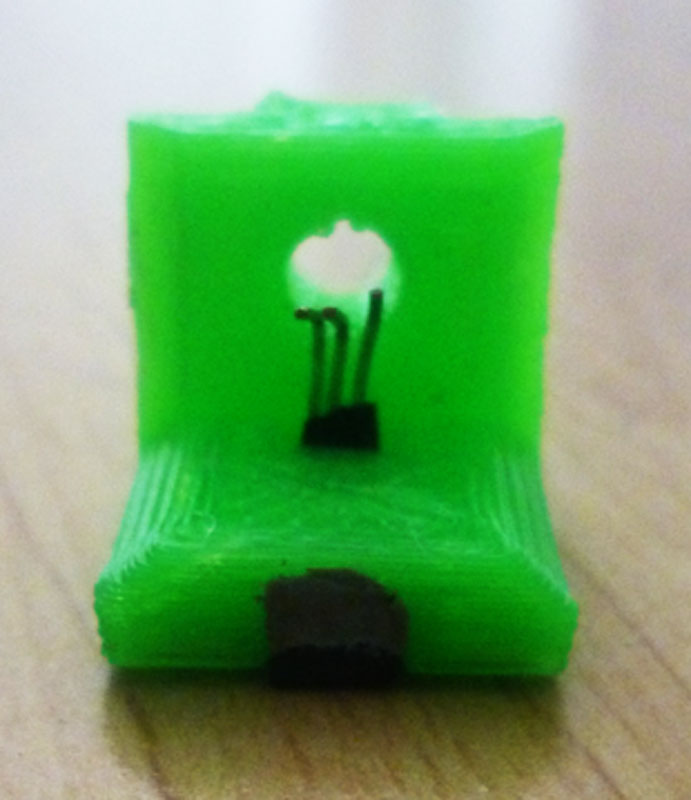
I have pre-insulated the pins with some electrical tape to prevent unwanted contact of the neighbouring pins.
View from underneath.
Here are all three after I removed the sensors and then manually countersunk for the M4 screws with an 8.5mm drill and then re-assembled.
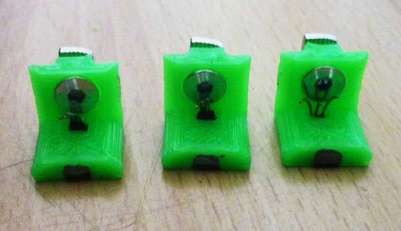
I actually turned the drill by hand rather than under power on my mini mill to give me more control of how much material was being removed.
I have two sets of very sharp, precision ground HSS metric drills, from Chronos in 0.1mm increments covering 1-6mm and 6-10mm respectively. I use these whenever I require a very sharp or accurate drill, most of the rest of the time I use a more generic set of drills.
The hall effect sensors were $4.00 (£2.58) for 10 from ebay seller gc_supermarket, the M4 T-nuts were $7.50 (£4.85) for 100 from robotdigg, and the countersunk M4 screws actually came with hinges I bought for my laser cutter where I used some slightly longer screws instead, so these were effectively free.
The total cost for the completed endstops is therefore 0.06 + (3 x 0.258) + (3 x 0.0485) = £0.882 ($1.35).
Here are some coils of wire I made up for the endstops, they are each about a metre long and are made from 3 cores of a 50m reel of 6 core alarm cable I bought from Wickes for £12.49 ($19.35) back when I was building my Prusa I3, so about £0.25 each.
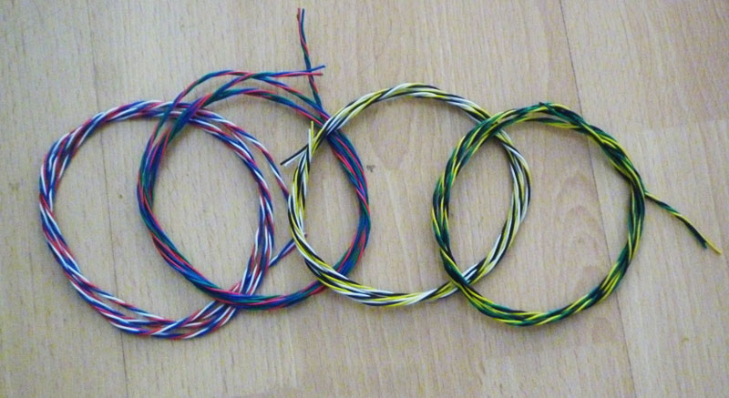
Mixing up the various cores allows each cable to either be the same or different depending on what you require at the time.
I tend to leave the outer protective sleeve on for the 4 core motor wires, but twist any signal wires to help avoid any cross talk interference, should the signal wires need to run together with the motor wires.