I was browsing through the new items on Thingiverse when I found an item that made use of a screen and referenced a different firmware – Marlin.
I had a quick read and thought it would be worth a try, cloned the github repository, downloaded yet another version of Arduino (0.22), I now have 4 different versions installed!
Adjusted the configuration.h file and compiled – first stumbling block, seems a fair bit more configuration is required, not exactly an out of the box solution!
Some more tweaking of the various pin header files later and we have something that will at least compile.
The preferred serial speed is 250000, so I updated my other bluetooth module to the nearest approximation of 230400 and adjust the Marlin config accordingly, communications work seamlessly.
I was having a closer look at the pins intended for use with the LCD and it would appear that since this code was originally written for use on an Ultimaker, or Arduino Mega based Ramps board, where there are loads of I/O pins to spare, I was going to need to define some alternatives for me to be able to use the available pins on the sanguinololu board that I am using.
There are just about enough available – I need 6 pins for the LCD, 1 for the SD card, 3 for the encoder, and one for the beeper – there are 10 available, so I will have to forgo the beeper.
Pin definitions as assigned in Sd2PinMap.h for available pins as I have chosen to use them are:
| Physical Pin # | Pin Name | Assigned Pin # | Use |
|---|---|---|---|
| 40 | A0 | 31 | SD card SS |
| 39 | A1 | 30 | Encoder 1 |
| 38 | A2 | 29 | LCD RS |
| 37 | A3 | 28 | LCD EN |
| 36 | A4 | 27 | LCD D4 |
| 5 | B4 | 4 | LCD D7 |
| 22 | C0 | 16 | Encoder C |
| 23 | C1 | 17 | Encoder 2 |
| 16 | D2 | 10 | LCD D5 |
| 17 | D3 | 11 | LCD D6 |
Some of these pins are labelled differently on the sanguinololu board: B4 is shown as D12, C0 as D16, C1 as D17, D2 as D10 and D3 as D11, these can all be determined by looking at the Extension Header section of the sanguinololu schematic.
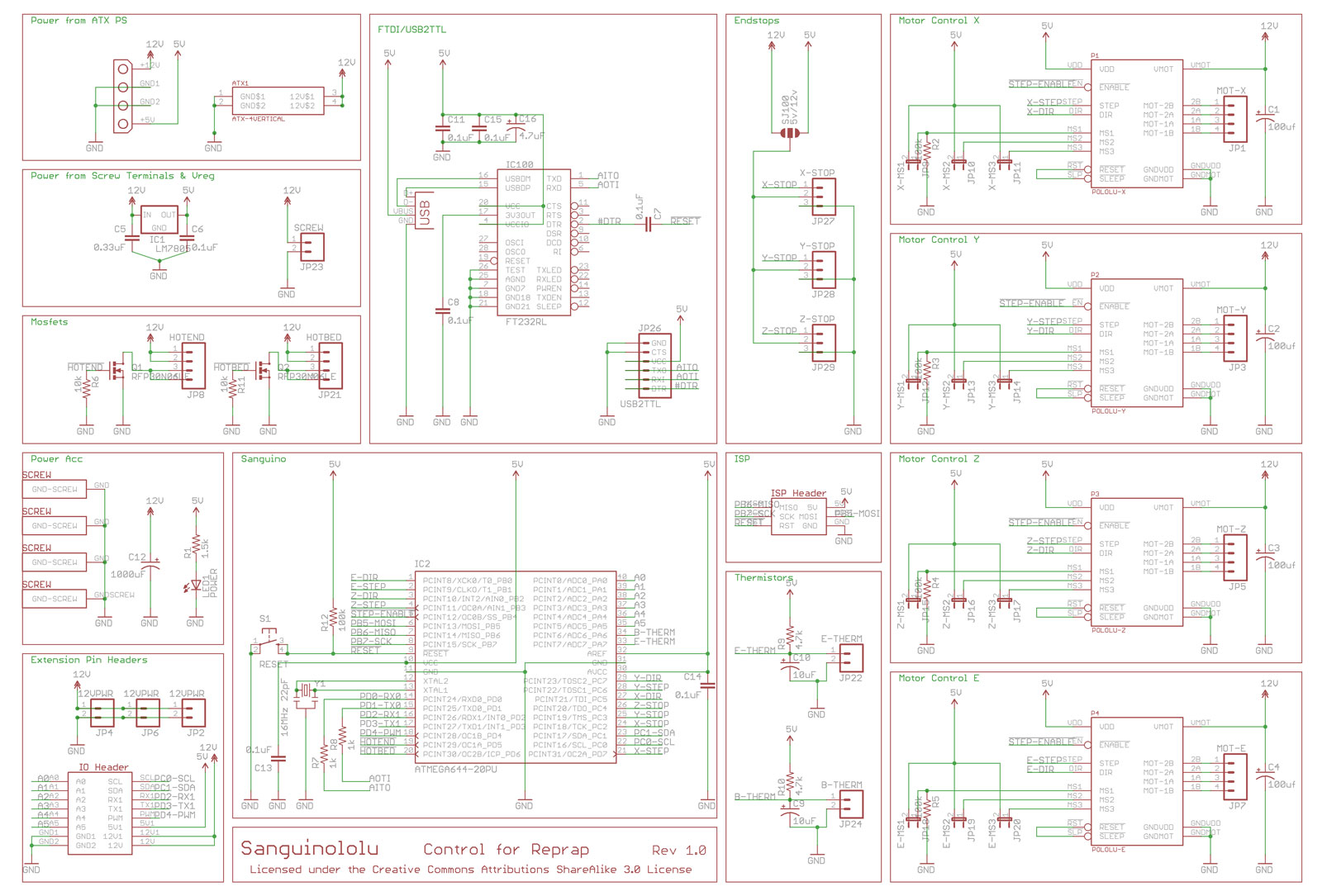
Having spent enough time playing on the breadboard, I decided it was high time I actually soldered up the board.
I have another ATmega644p chip, so the one I have been testing is still on the breadboard.
I followed the instructions on the Reprap Wiki regarding what order to install the components, but left out all of the ones associated with the FTDI chip.
Looks like my Soldering skills aren’t too rusty after all.


