Having finally decided on a layout for the plate in the control box, I decided it was time to drill and tap the holes for the motherboard and stepper drivers.
The plate itself was previously used for something else, and so there are other extraneous holes dotted around the plate.
16 x M3 holes later, I attached all of the stepper drivers, the motherboard and the two breakout boards.
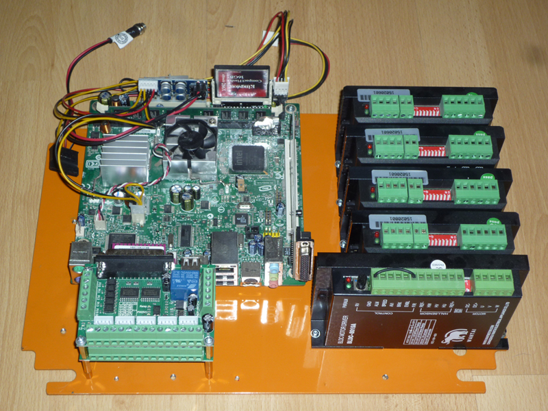
The motherboard is sat on 10mm M3 spacers, the breakout boards are separated by 20mm spacers.
30mm of spacer brings the bottom breakout board to the right height to attach directly to the parallel port on the motherboard.
There will be a ribbon cable connecting the second breakout board to the PCI parallel port card.
There are 4 stepper drivers, for X, Y, Z and a rotational axis, the larger driver is a BLDC driver for running the spindle of the 4th axis ‘lathe’
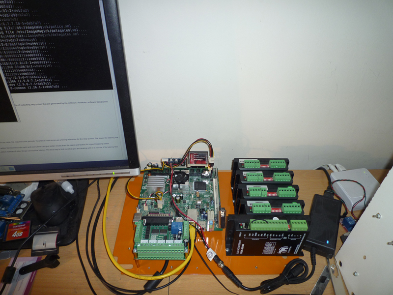
I decided that I did not like all of the extra wire associated with the Pico-ATX power supply and so I modified it to just have the required wires for my installation.
In this picture, you can see it powered up and installing updates.
Here is a close-up of the wiring modification – I merely crimped new ends on the 4 pin floppy drive connector to replace the SATA and Molex connections.
Next I started drawing up a schematic in Visio.

This is not a complete wiring diagram at present, more a work in progress.
I then proceeded to wiring the stepper motors to the breakout board.

The yellow wires are for ‘step’, the green for ‘direction’, the white wire is for ‘enable’ and the brown wires are 5V for the positive sides of step, direction and enable.