My Makerslide arrived this morning from myhobby-CNC in Germany, just 2 days after placing my order.
I should now have most of the pieces required to finish off the frame – I still need a few spacers for activating micro switches, raising the rear mirror mount and stops for the lid, but otherwise I should be good.
I tapped the ends of the Makerslide, fitted the end plates and then added the 3 lengths of Makerslide to the frame.
Unfortunately several of my printed idler pulleys decided to split
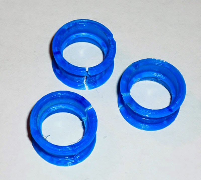
obviously I did not bore them out quite enough and the force of pressing the bearings into them has caused them to fail.
Still the overall cost of this attempt was only £0.05 plus some time, so onto the next version:
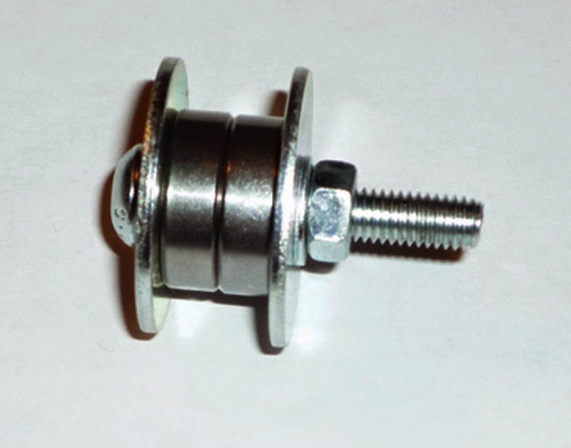
M5 penny washers from Orbital Fastners at £2.71 ($4.20) for 100 and bare bearings, this concept works just fine on my 3D printer, so why not here? The above is just an example, most of them have been put together using nyloc nuts so that the nut stays put even if not fully tightened against the washers.
New additional cost £0.22 ($0.34) for 8 penny washers, still not up to the cost of 1 Delrin idler pulley at £1.68 ($2.60) for just the wheel, or £3.26 ($5.00) for a complete wheel kit from Openbuilds, and £3.25 ($5.00) for a complete idler wheel from Amber Spyglass, since I need 4 of these the cost would potentially be around £13.00 ($20.00).
My cost for a complete idler wheel is: 2 x 625 bearings (2 x £0.161), 2 x penny washers (2 x £0.0271), 2 x M5 washers (2 x £0.0041) 1 x M5 nyloc nut (1 x £0.0116) 1 x M5 x 40mm button head set screw (1 x £0.0697) = £0.4657 ($0.72), so for 4 idlers my cost is £1.86 ($2.89), a saving of over £11.00 ($17.00).
I could also have added some normal washers between the bearing and the penny washers, however this can lead to the belt deciding to bend into the gap if it has any tendency to move about laterally.
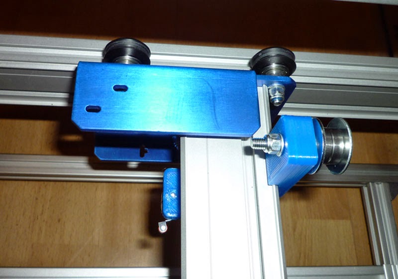
This is one of the Y axis idlers where I have used a couple of extra M5 nuts as spacers:

You can also see from this picture that I chose to mount the Makerslide using standard 90 degree brackets on the inside of the frame, rather than using the special narrower Misumi brackets underneath the Makerslide.
Here is the X idler at the end of the Gantry
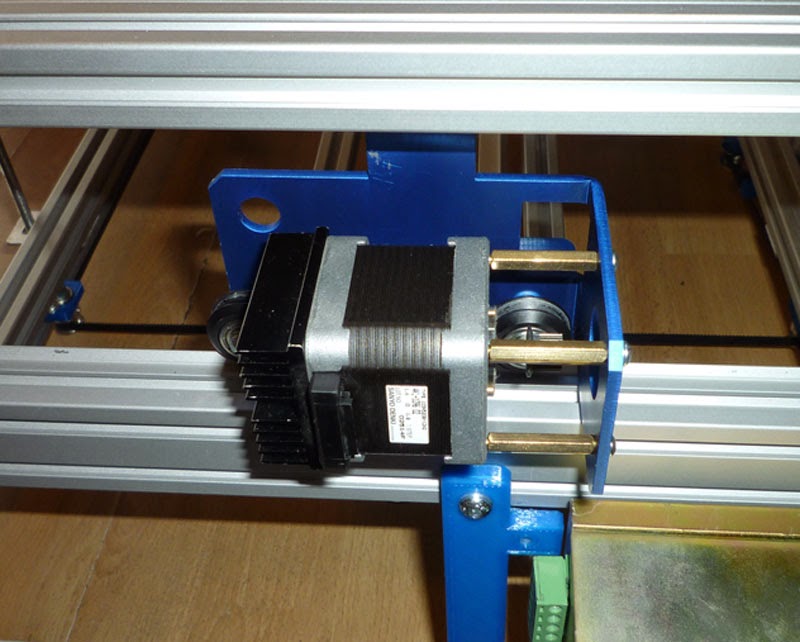
and the motor installed on the other end
I cut 4 lengths of M6 studding/all thread from a 1m length and started to assemble them
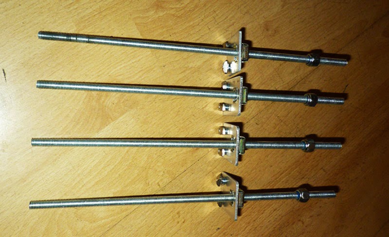
I later realised that only 3 of them actually required the nyloc nut.
Here are the 3 completed items with the various parts all spaced to the correct dimensions for mounting on the frame.
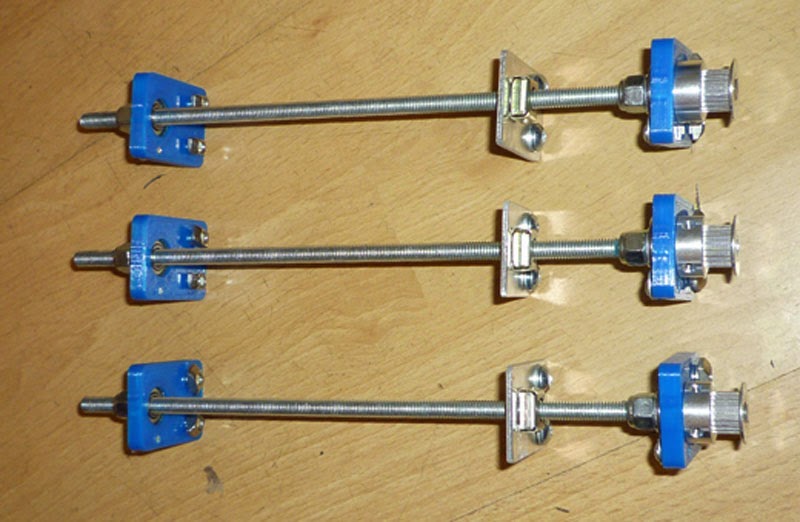
There is a second nyloc nut at the top of the stack just to ensure it all stays together, the pulleys on the bottom are all 20 tooth GT2-2 with 1/4″ bore (just over 6mm).
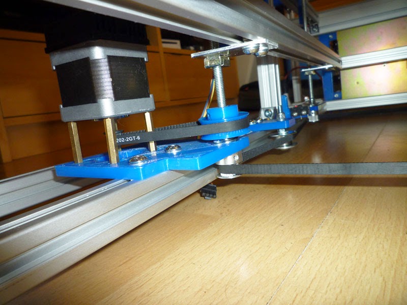
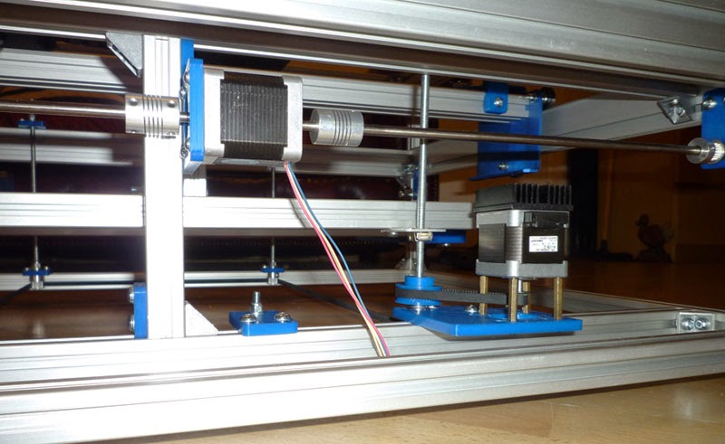
I then assembled the gear reduction for the motorised leg using my 3D printed 48 tooth GT2-2 pulley and a 202mm, 101 tooth GT2-2 belt.

The gear on the motor is actually 15 tooth, this came with the motor, I will use this for now, but may switch it out for a 20 tooth at some point, although this gear should give me even greater resolution on the Z axis.
Finally I installed them all in the frame and added the 1524mm, 762 tooth GT2-2 belt and the Z axis idler.
Here is the completed Z axis installed with the almost complete rotary engraver in place – it still requires a slightly longer belt (because I originally guessed at some of the hole locations and was out by a few mm) and a pulley for the stepper motor (this build will be covered in a separate post).
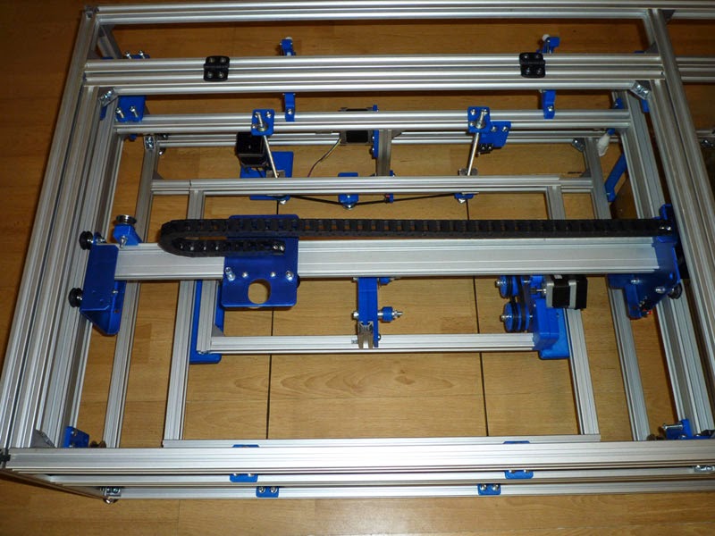
I needed to trim a few mm from top the rear 700mm length of 20×20 extrusion that holds the top of the Z axis mounts so that it would fit between the 2 lengths of Makerslide.
As you can see from this picture, I also fitted the X axis drag chain and was eventually happy with the length after 3 adjustments – it turns out I only needed a 1m for this axis after all and still had some left over.
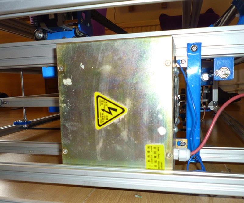
I was now able to fit the high voltage power supply using the brackets I had printed.
The 6mm precision rods that I used for the Y axis both came from scrapped inkjet printers, so again these were free.
Next I installed the belts for the X axis
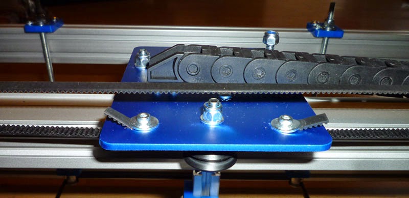
and the Y axis.

These used M3 x 16mm cap head screws, M3 nyloc nuts and an M3 x 12mm penny washer on each side.
The belt was left over from building my 3D printer which cost $29.00 (£18.70) with free shipping for 10m (393″ or 32′ 9″) of 5mm wide GT2-2 belt.
The belts on the laser cutter are approximately 2 x 1m (40″) and 1 x 1.5m (60″) , so 3.5m (140″) of belt cost me (18.70 / 10 * 3.5) £6.55 ($10.15).
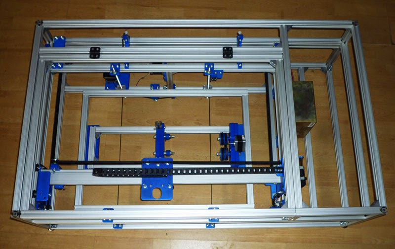
Mechanical build almost complete.