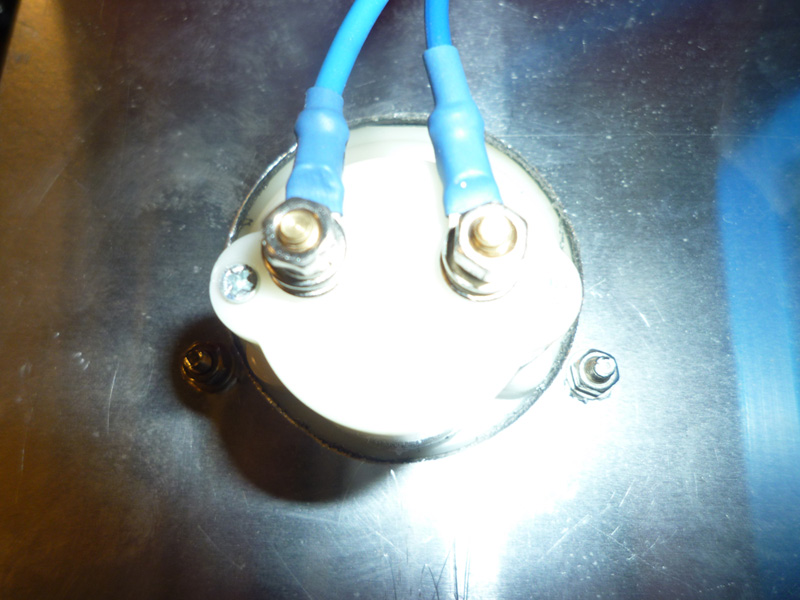
The ammeter is wired in series with the negative for the laser PSU.
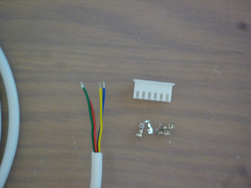
For the motor wiring, I am using 6 core alarm flex from Wickes, but I pull out 2 of the cores first, I use these elsewhere for limit switches and other low voltage wiring.
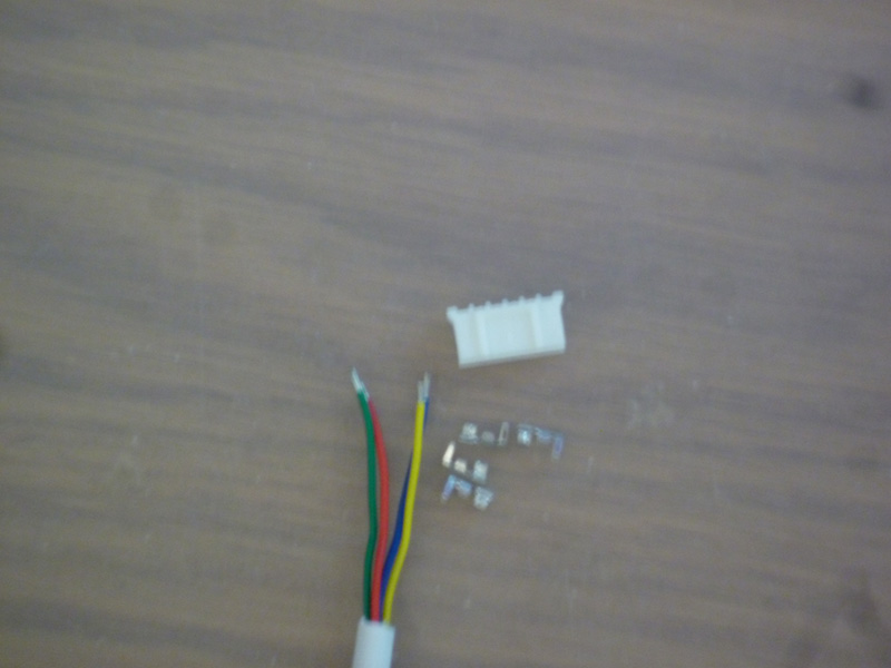
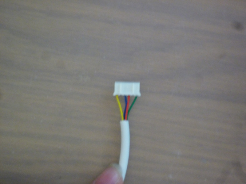
I have 3 different sets of connectors on my various stepper motors, the X and Z motors use a JST EH 6 pin 2.5mm pitch 6 pin connector and crimp pins.
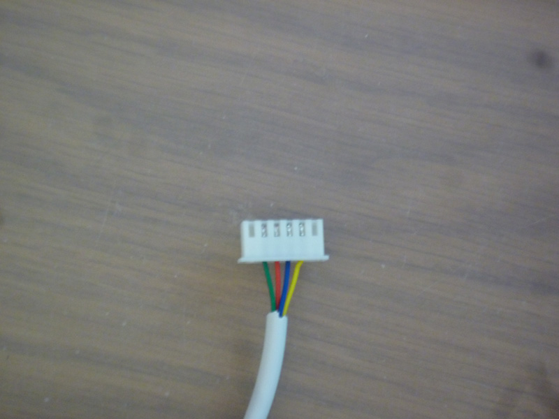
completed connector
The rotary axis uses a JST 6 pin 2mm pitch connector and associated crimp pins.
completed connector
I checked which pins make up which coils before wiring the connectors, you will note from the above pictures that the different motor types are also wired differently.
The Y axis motor is a dual shaft motor that has wire tails, so I will just extend these.
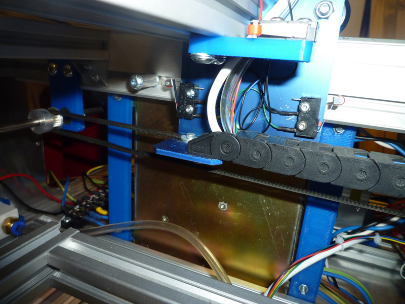
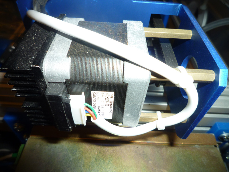
This shot shows the X axis motor
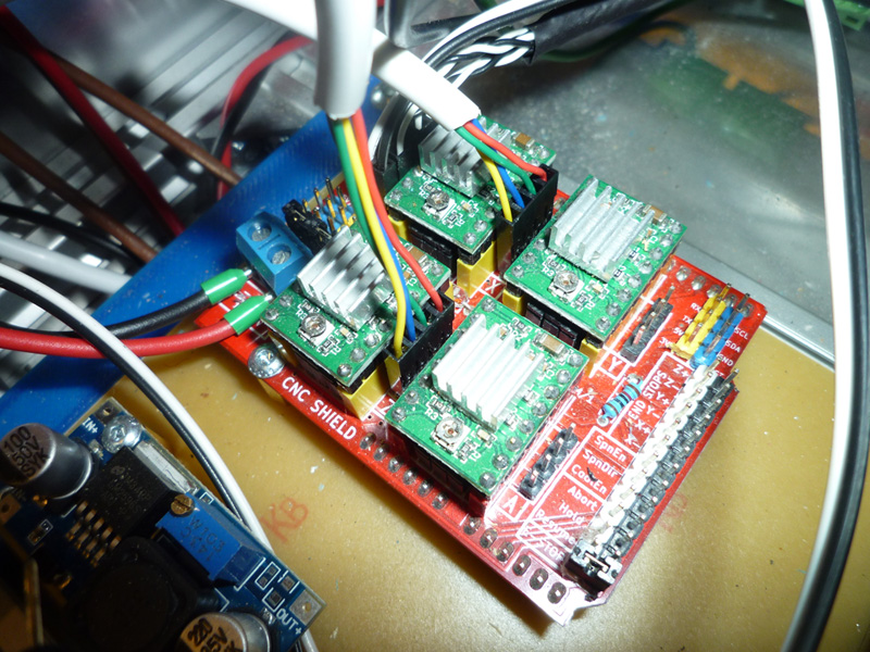
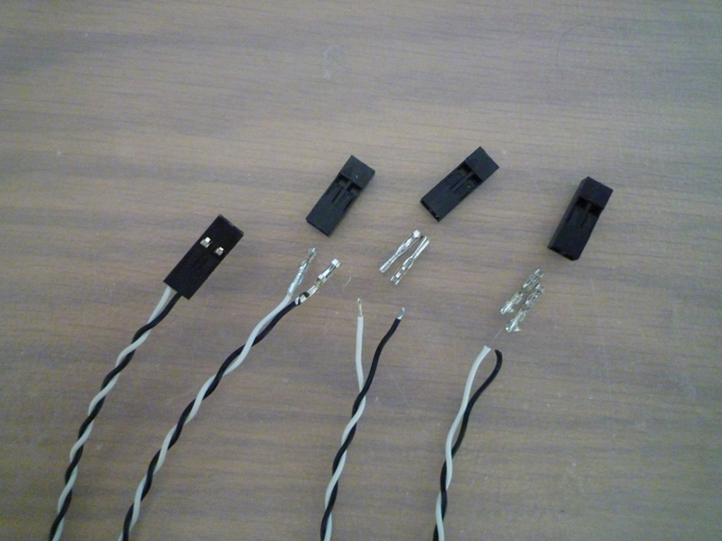
The other ends of these cables will make use of 4 pin DuPont connectors to attach to the Protoneer stepper board.
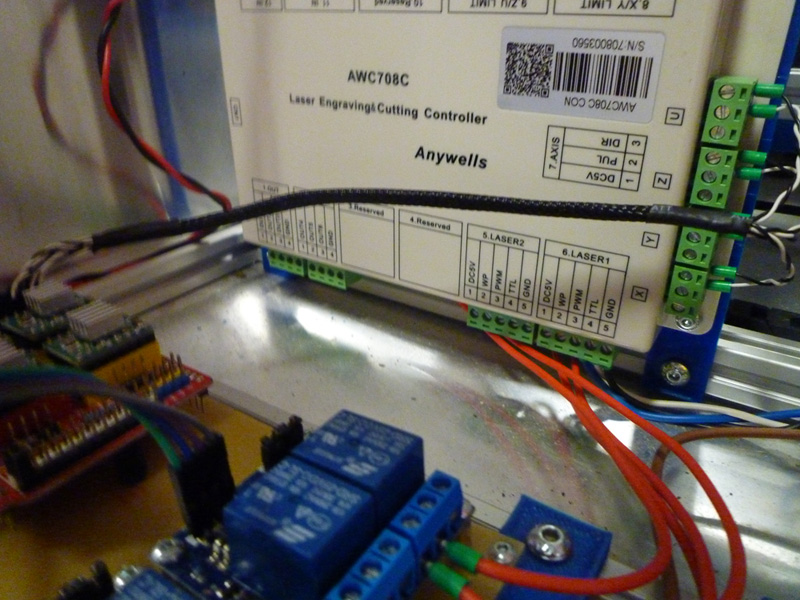
For the step/direction signals from the DSP to the Protoneer stepper board I made use of some of the spare cores from the motor wiring, using bootlace ferrules on one end.
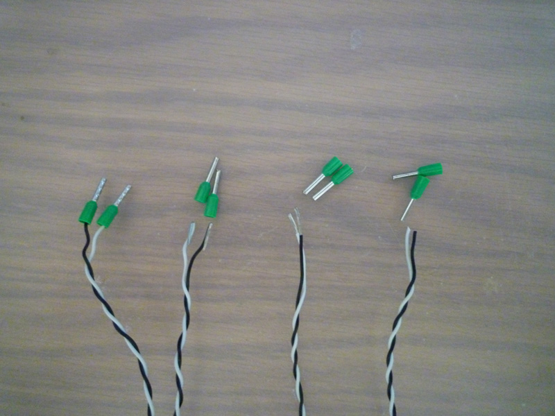
and DuPont 2 pin connectors on the other
all 4 cables made up
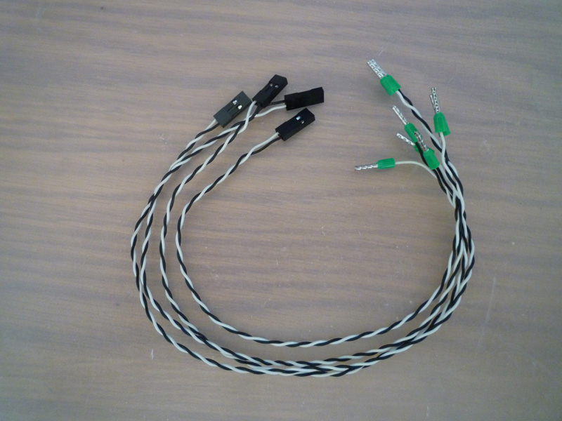
and then wrapped together with some expanding sleeving – I made sure to label both ends before wrapping them all together.
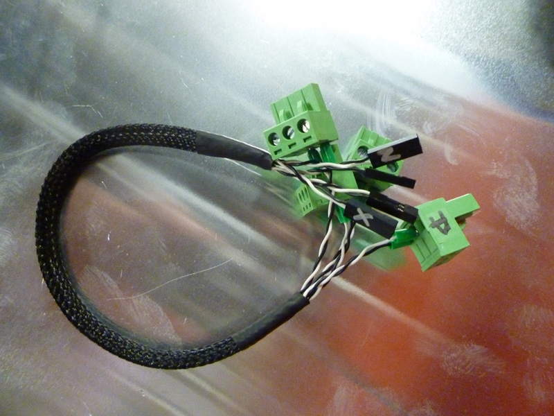
cables in place
Next I started on the limit switch wiring, this again made use of individual cores from the alarm cable, the X and Y wiring makes use of a shared ground wire but individual signal wires.
The wire cores are soldered to the microswitches on the one end, and have bootlace ferrules on the other.
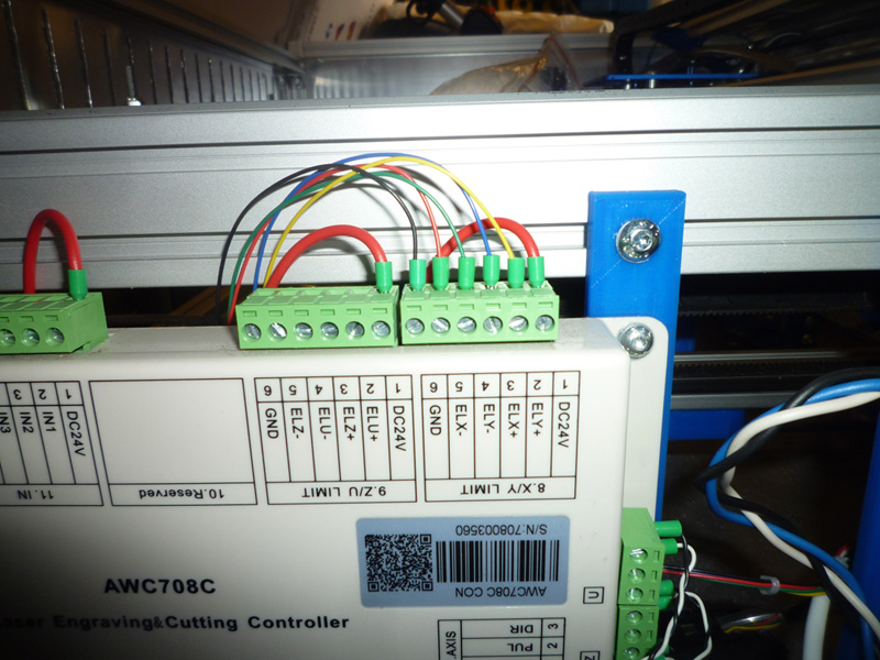
This shot shows the Y min, max and X max microswitches, you can also see that the X motor wires, limit switch wires and air tubing are all routed through the energy chain from the base of the cutter to the Y axis gantry.