Close

The Build Part 7 – Wiring for Power

For the wiring, I started with the 240V and 24V power wires.
You can see from the below photo that I have a few colours to choose from, most of these spools are left over from when I rewired my Beach Buggy, the vertically stacked ones are from wiring up the lights in the garage.
The 240V wires follow the standard EU colouring scheme of Blue for Neutral, Brown for Live and Green/Yellow for Earth or CPC.
The front switch has 3 positions and uses a NO and a NC set of contacts.
  • Position 1 both the 24V and Laser power supplies are off
  • Position 2 only the 24V PSU is live
  • Position 3 both the 24V and Laser power supplies are live.


The E-Stop has two NC sets of contacts and if pressed will remove 240V power from the Laser PSU and 24V power from the stepper shield, thereby stopping anything that could potentially cause damage, i.e. the laser and motors. The DSP, extractor fan, cooling pump, and anything else that runs on 24V or 5V will continue to run.
24V wiring uses Red for +24V and black for ground.
5V and signal wiring uses a variety of colours based on what was next on the strip of tear off cables.

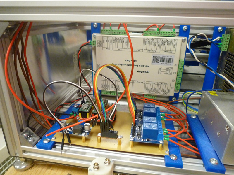
The DSP is wired directly to the 24V PSU, the stepper shield is wired via the E-Stop switch, but again has a dedicated connection to the 24V PSU.

Rather than run multiple wires from the 24V PSU for the various relays, these each make use of a dedicated 24V output from the DSP, this also makes for shorter wiring.

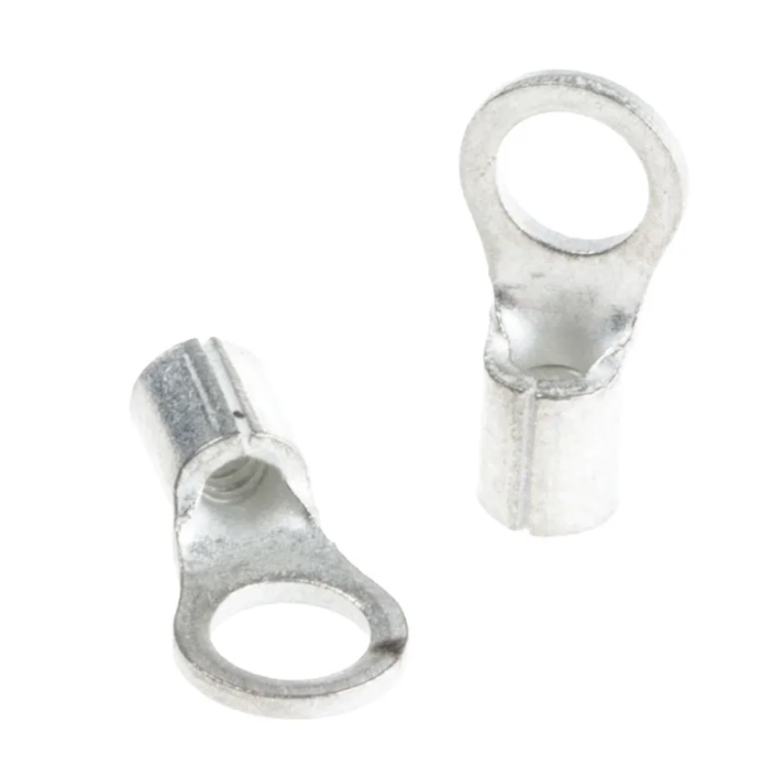
The power connections to the connector block and the 24V PSU are using 3.5mm ring connectors that are crimped onto the cables.

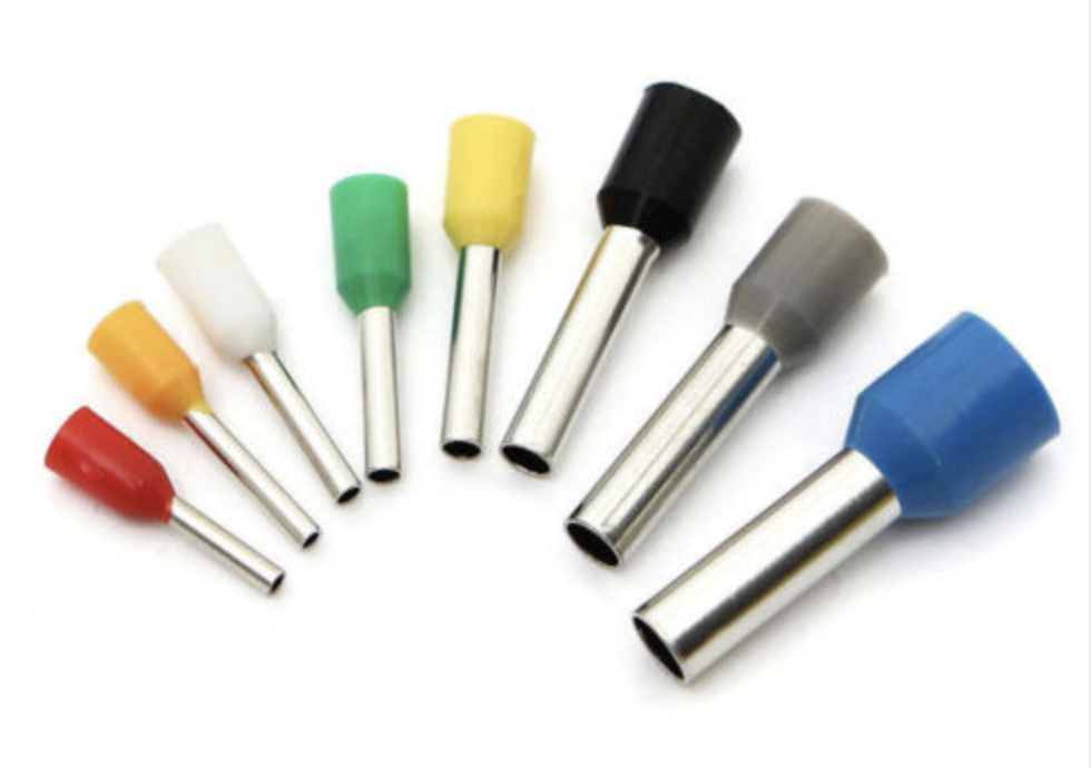
For the screw terminals I am using bootlace ferrule crimp connections

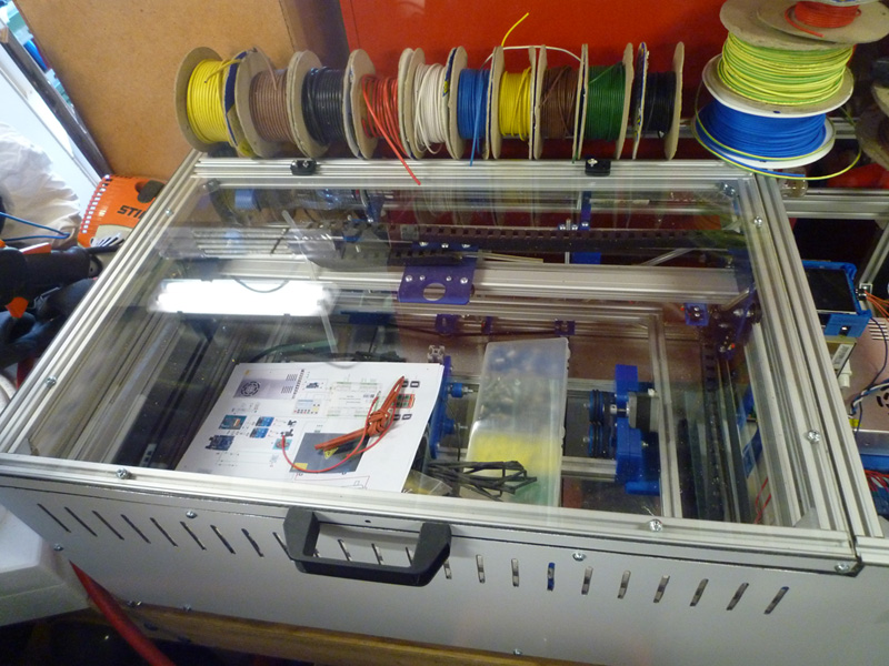
The shot below shows the wiring on the terminal block,

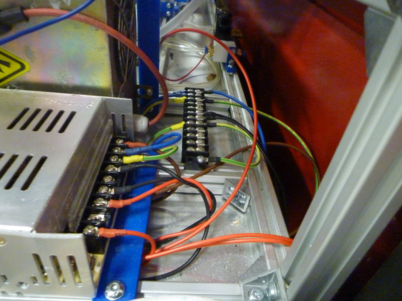
some of which goes out the back of the frame, this is for the extractor fan connector, pump connector and IEC inlet filter power connector.

At the time this photo was taken, I had not yet made the cutouts in the rear panel, so it had yet to be attached.

Leave a Reply