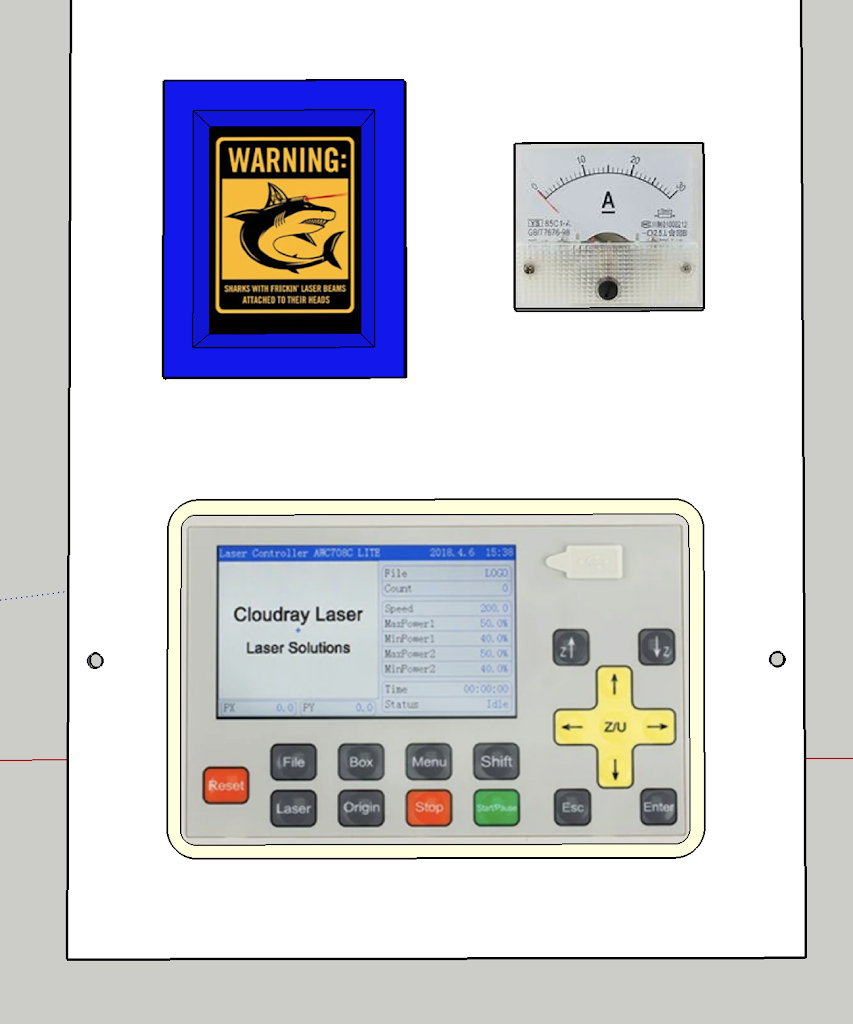
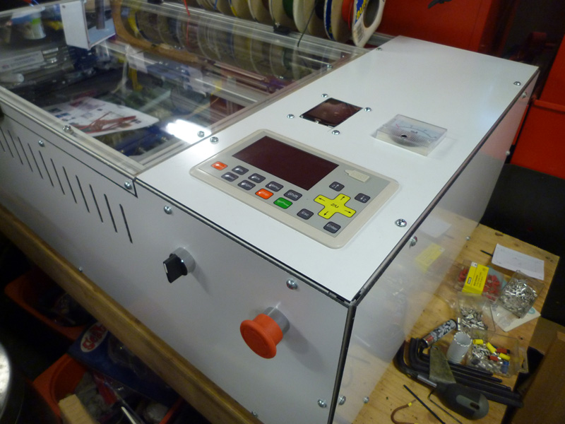
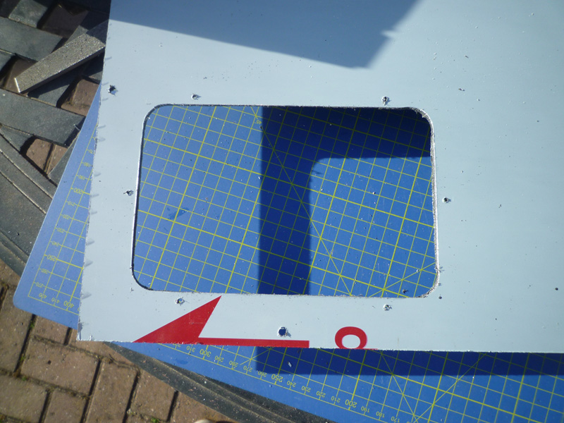
For the top right panel, I marked out all of the required openings and then cut the two square ones with a knife and the round one with a hole saw before drilling any required mounting holes.
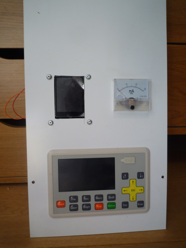
The Arduino screen will have a cover/surround that will hide the mounting screws.
I am not entirely sure how the DSP is supposed to be mounted, but based on the supplied mounting hardware the picture below shows what I believe to be something along the right lines.
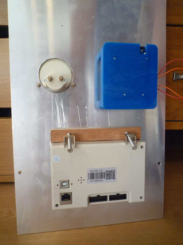
The piece of plywood is to protect the Dibond from the screws, the front edge has 3 tabs that allow the edge to slot into the 3mm Dibond.
I then re-attached the right side panel for a more complete corner shot.
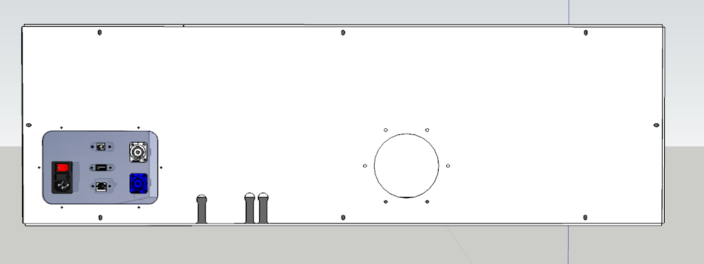
My rear panel design differs only slightly from the skins plan mainly because of the air solenoid.
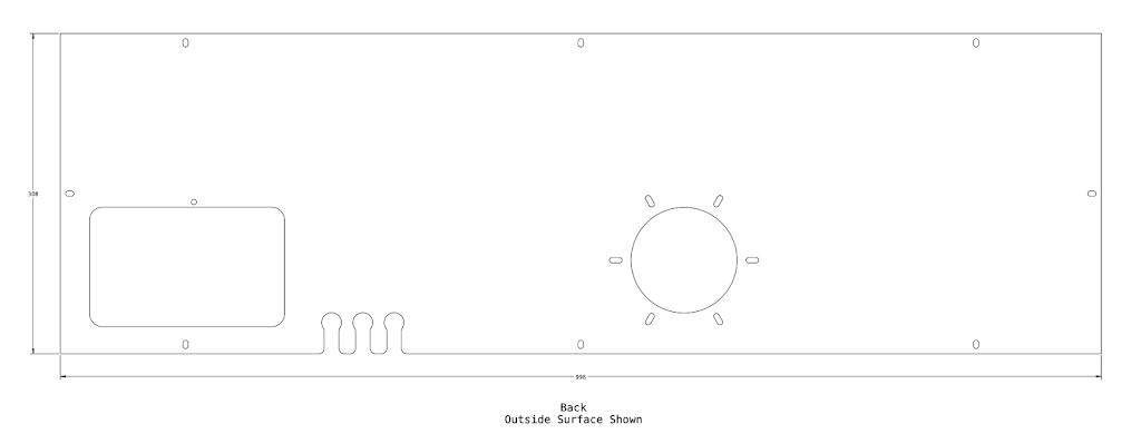
My version pushed the water inlet and outlet holes to the right, plus I have allowed for more mounting holes on the I/O panel.
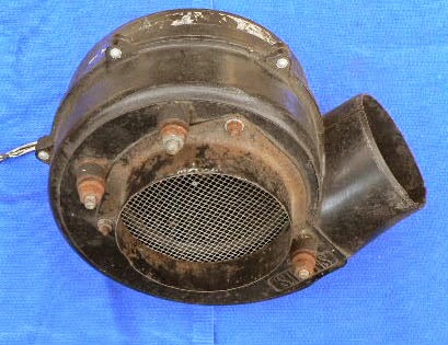
The duct I am using is part of a kit for a tumble dryer exhaust extraction that I never used, so this is another free part, this duct is just under 100mm in diameter and I will also use the hose that came with the kit to attach to my bilge blower.
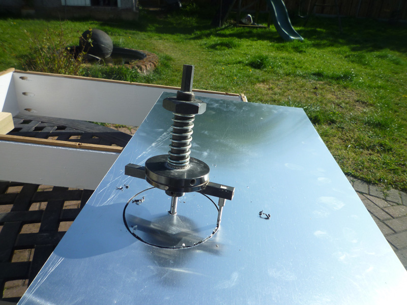
To cut the hole for the duct, I made use of my Draper adjustable radius hole cutter (#59470), this can cut holes from 30-163mm in diameter in a variety of materials up to 45mm thick (if drilled from both sides) and aluminium or brass up to 1mm thick.
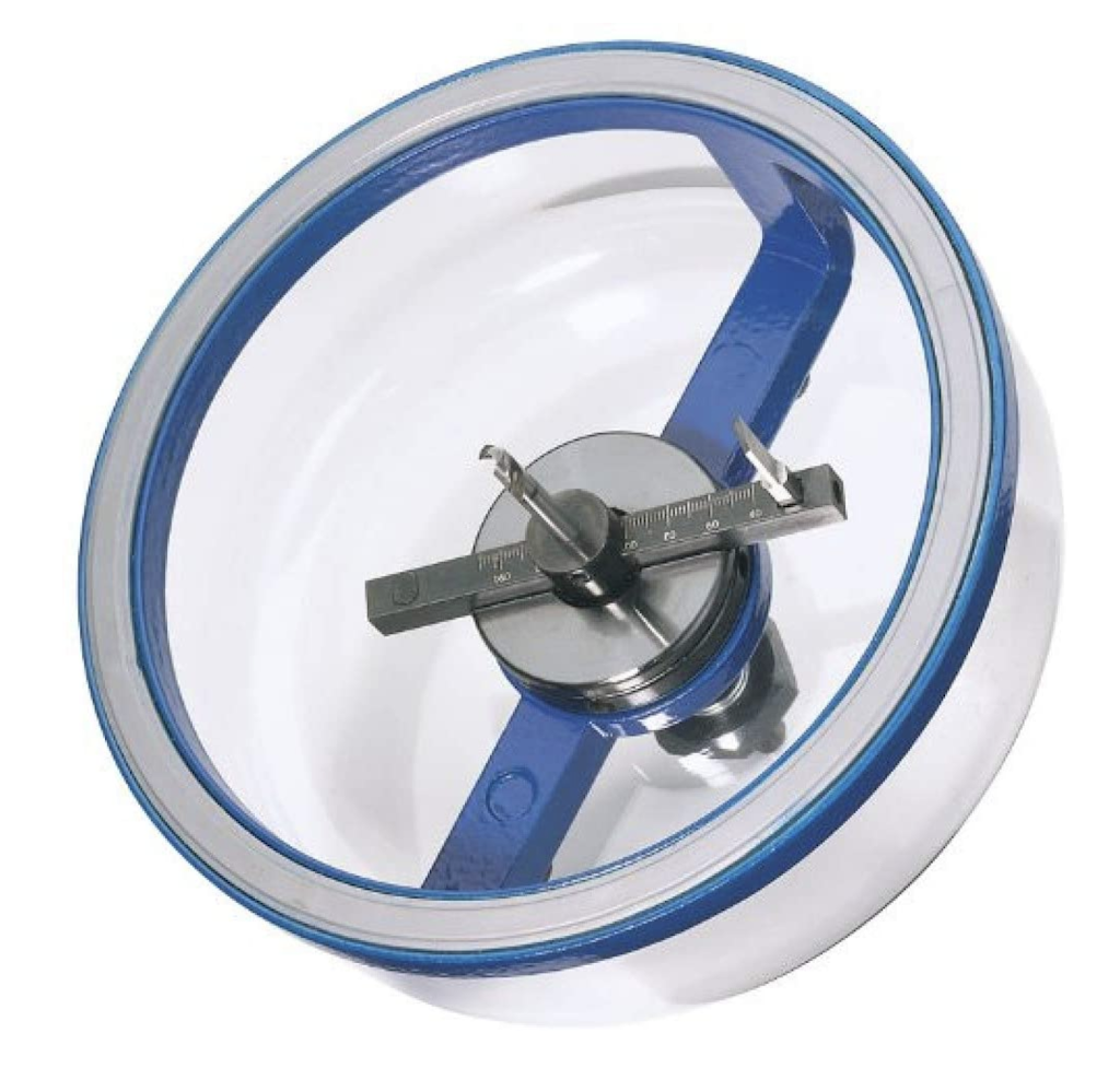
There is a spring between the cowl and the drill that allows you to press slowly into whatever you are cutting and the cowl keeps the cutter perpendicular to the surface.
The cowl is extremely useful when cutting holes in ceilings as it collects all of the dust that would otherwise fall on you.
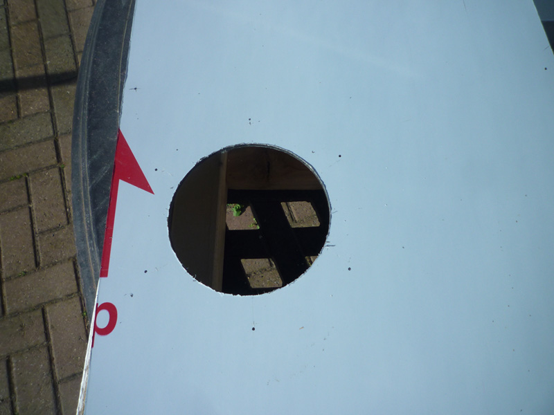
This image shows the cut part way through but with the cowl and drill removed.
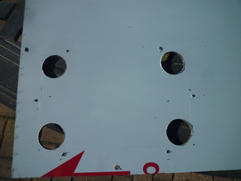
The finished hole with markings for the fixing holes.
For the I/O cutout, I first drilled the corners that have a 15mm radius with a 30mm forstner bit
then joined up the holes using a Stanley knife and drilled the 3mm mounting holes for the I/O plate.
Next I drilled the holes for the water and air hoses, enlarged them to 16mm and then turned them into slots with a handsaw.
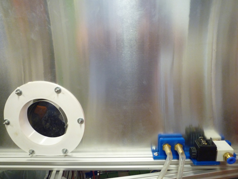
Here is the finished back plate with the duct attached and showing the air inlet and water barbs, the bracket assembly for these is attached to a spare piece of 20x20mm profile to check everything fits.
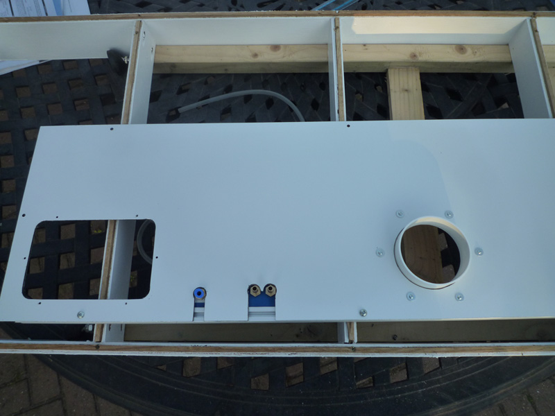
The bottom of the duct surround required a slight trim to clear the profile, the duct also makes use of a foam seal that came with it that also required trimming to size.