I have now printed all of the parts for the rotational axis
The 350m reel of blue PLA was slightly more expensive than the black at £13.09 as opposed to £11.99, therefore the cost to reprint the laser cutter parts went up from £2.358 to £2.574.
Cost of the printed parts for the rotational axis:
| Filament | Cost | Total | ||||
|---|---|---|---|---|---|---|
| Part # | Description | (mm) | (cm3) | (£) | Qty | (£) |
| B17024 | Drive Wheel | 7136.2 | 17.2 | 0.267 | 2 | 0.534 |
| B17025 | Idler Wheel | 613.8 | 1.5 | 0.023 | 1 | 0.023 |
| B17026 | Idler Wheel, Flanged | 810.8 | 2 | 0.303 | 1 | 0.303 |
| B17027 | Idler Support Bar, Horizontal | 7800.8 | 18.8 | 0.292 | 1 | 0.292 |
| B17028 | Idler Support Bar, Angled | 12216.0 | 29.4 | 0.457 | 1 | 0.457 |
| B17029 | Drive Wheel Support | 22964.5 | 55.2 | 0.859 | 1 | 0.859 |
| B17030 | Drive Wheel Support, Notched | 20663.1 | 49.6 | 0.773 | 1 | 0.773 |
| B17031 | Base, Motor End | 26101.0 | 62.8 | 0.976 | 1 | 0.976 |
| B17032 | Base, Idler End | 25618.2 | 61.6 | 0.958 | 1 | 0.958 |
| Total | 4.902 | |||||
Milling the parts from a 12mm sheet of HDPE would definitely have been much faster, however the cost an A4 sheet would have been 3 times the cost for the raw material.
Some of the bearings were not the best fit in the Z lift plates, so I decided not to spend extra time and potentially waste large quantities of plastic on trial and error and simply printed the drive wheel support bearing holes slightly under size and then bored them out to a good friction fit on my Mini Mill afterwards.
Here are all the printed parts with their bearings, T-Nuts, etc installed.
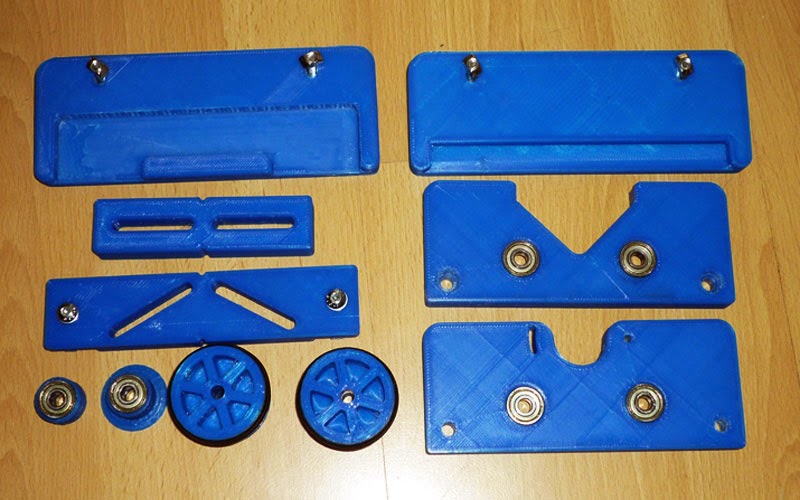
The bearings were £2.89 for 10 with £0.20 P&P from ebay seller seariver2009, the O rings (34.5mm ID, 3.5mm Section) were £1.10 and £0.55 P&P for a pack of 10 from ebay seller outsideleisure.
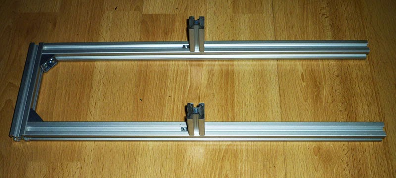
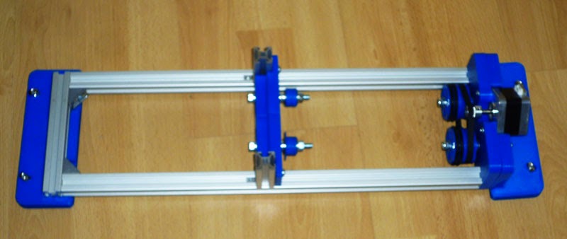
The 20x20mm extrusion parts assembled
The idler end assembled
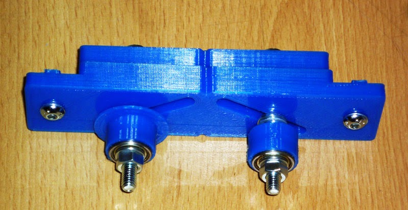
The Motor end assembled
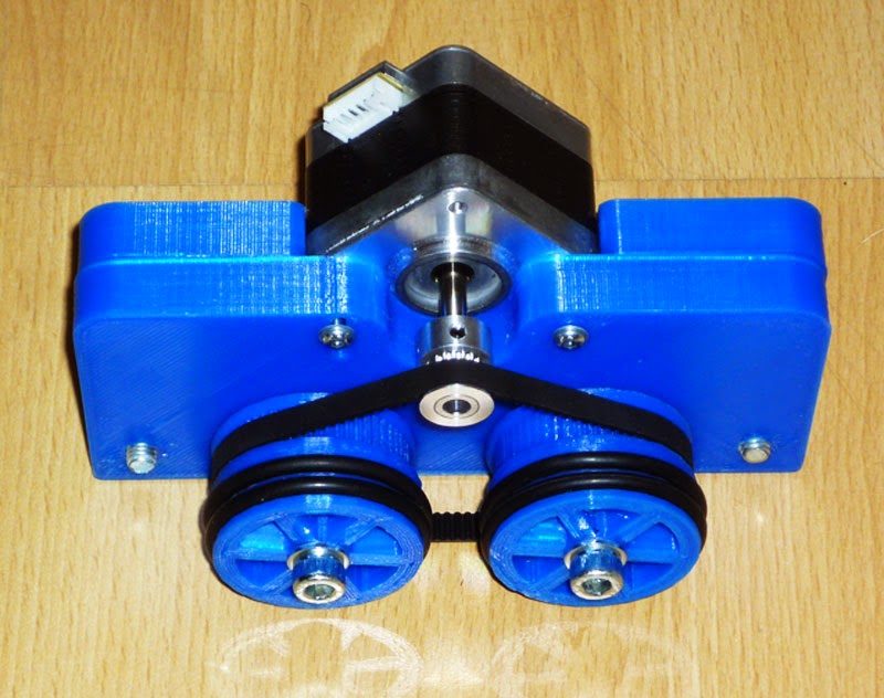
This uses a 16 tooth GT2-2 gear ($1.80) and a 232mm/116 tooth GT2-2 belt ($0.50), both from Robotdigg.
The full assembly
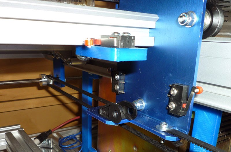
The brackets installed on the Z axis
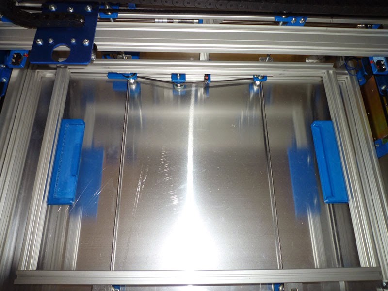
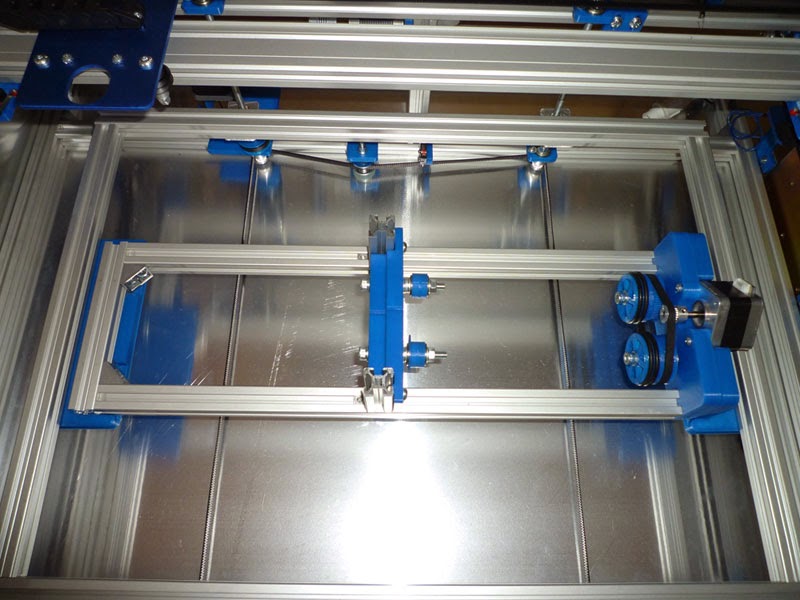
The Rotational axis installed on the brackets
I ordered the skins from Plasticsource for £38.00 + £17.00 P&P for a 2440x1220mm (4’x8′) sheet, this included cutting the panels to size, although I am still awaiting delivery of the offcuts, or some other similar sized pieces, as they failed to send these with the original order.
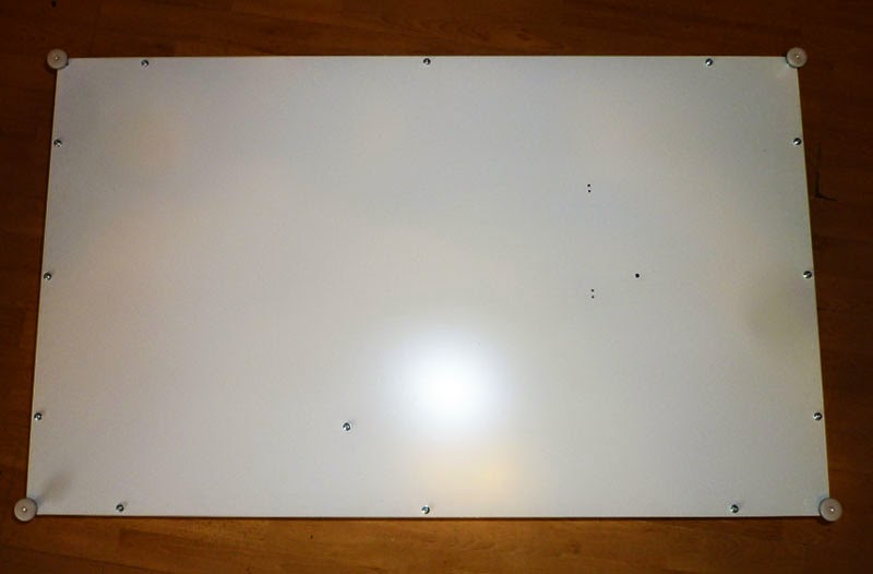
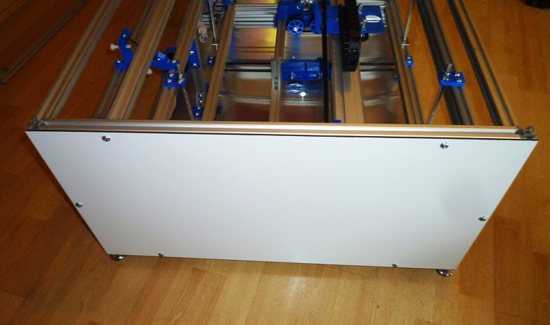
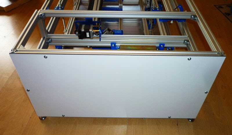
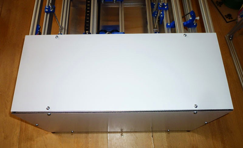
I drilled the various mounting holes in some of the skin panels and then attached these to the frame:
The base
Left end
Right end
Right top
Rear top
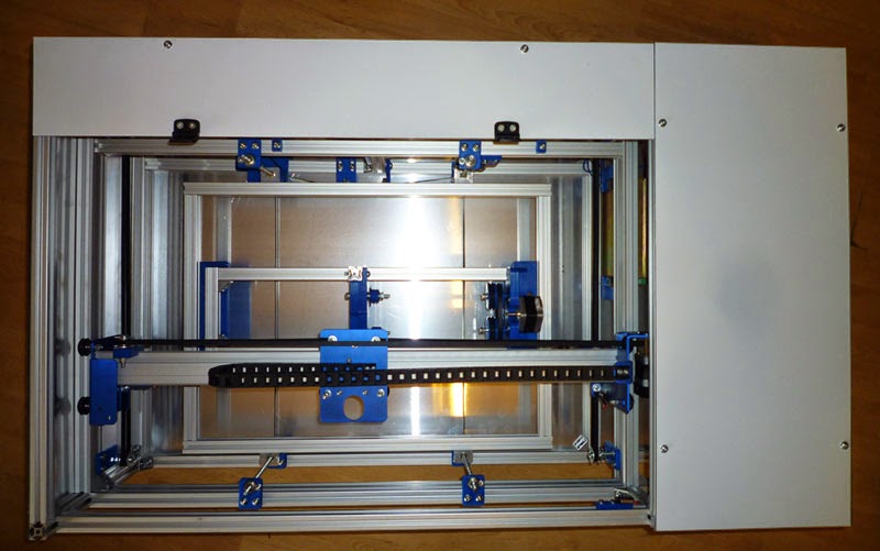
I have yet to cut the relevant holes in the front and rear panels, as well as make the strip for the top left.
I also need to obtain a suitable piece of 3mm clear acrylic for the lid.
When I came to trial fit the laser tube, I hit another issue – the mounts have a 55mm diameter hole, but the tube is also 55mm diameter, so it does not fit!
As a result I printed a new set of mounts with a 60mm diameter hole.
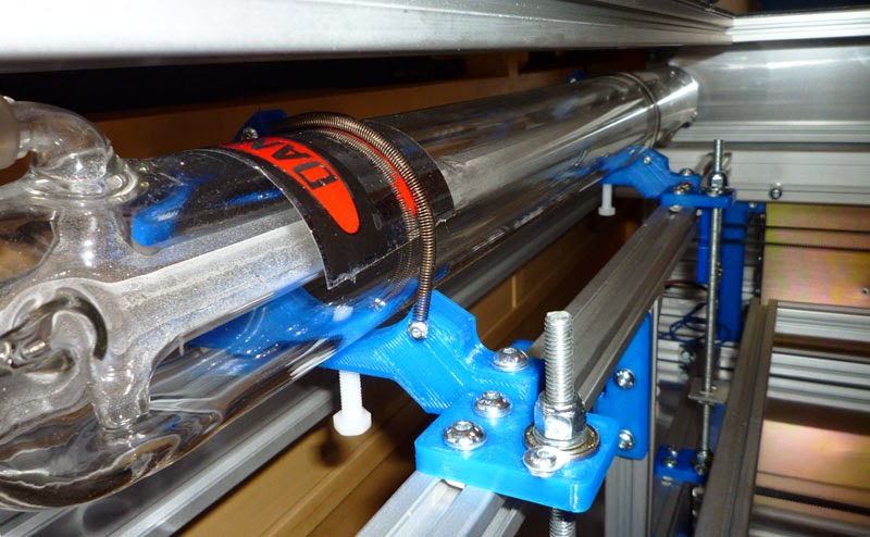
The tube now fits perfectly, however as I suspected, I will be needing some stiffer springs for retaining the tube in the mounts.
I also decided that for the sake of a few extra pennies worth of plastic, some wire and an extra couple of micro switches, I would add maximum travel limit switches to both the X and Y axes to complement the minimum limits as well as to match the Z axis.