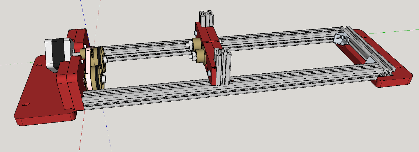
Bart Dring provides all the details of the rotational axis to his Buildlog.net laser cutter here.
Unfortunately for me he only supplies the detail for the parts in the STEP file available on the Wiki.
Don’t get me wrong STEP files are potentially one of the best ways of supplying 3D information, however I don’t currently have any software installed that can read them.
I used the Bill of materials as a baseline for the frame parts and drew up all of the parts in Sketchup.
The only part I really struggled with was the gear near the motor, I knew it was intended to use an MXL belt, however I did not know the number of teeth on the gear and could only guess at the overall dimensions.
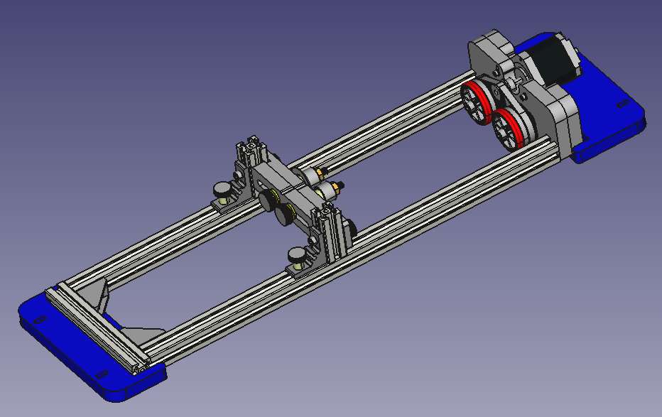
I eventually caved in and downloaded a copy of FreeCAD as this is capable of reading STEP files and exporting parts as STL files.
Here is the full model rendered in FreeCAD from Bart’s STEP file:
I was able to locate the gear after selecting through the various parts and export this as an STL file.
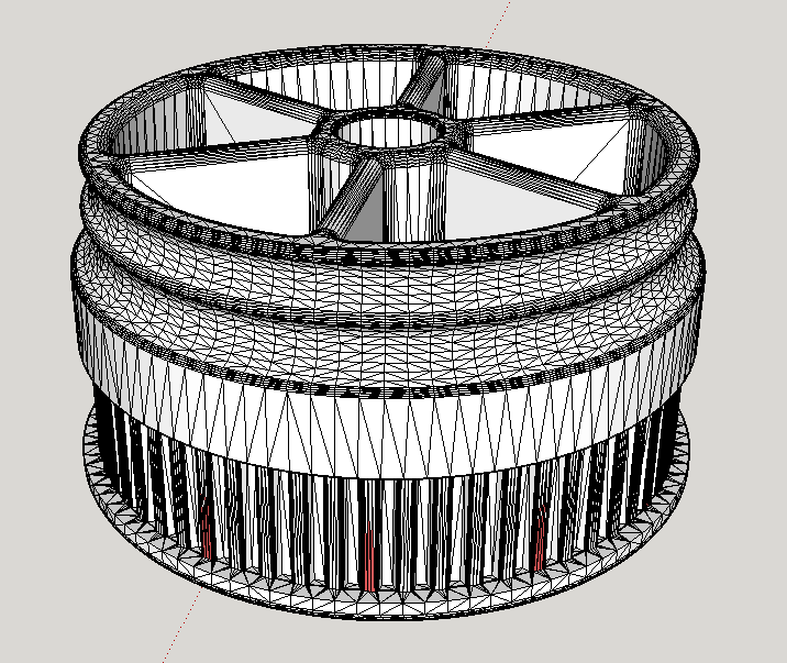
I could then open this is Sketchup and take some measurements and also count the teeth on the gear (hence the pink marks every 5 teeth).
I had no real desire to print this STL file as it was, since I don’t actually want to use an MXL profile belt, I would rather use a GT2 belt, as this is what I use on my 3D printers and also what I have redesigned the parts on my version of the Buildlog.net laser to use, plus all of my stepper motors came with GT2 gears pre-installed that would be a shame to waste only to have to purchase an MXL replacement.
MXL and GT2 are very similar in pitch (2.032mm for MXL and 2.0 mm for GT2) so there will be minimal difference in the diameter of the gear, however the tooth profiles are very different, GT2 is a more rounded profile and allegedly has very low backlash.
I have a parametric OpenSCAD script from Thingiverse that allows me to generate pulleys of any size and profile, so once I had determined that the original gear had 60 teeth in MXL profile I generated a gear with 60 teeth in GT2 profile.
I then exported this as an STL, imported it into Sketchup and removed the hub. I then used the dimensions from the original gear to make a new shell to insert my new GT2 teeth into and this is the result:

I then exported this as an STL file, sliced it with Slic3r and then printed it on my 3D printer.

I tested the gear mesh with the end of my 10m roll of GT2 belt and it meshed perfectly with no slip or movement whatsoever.
Happy with the print, I went ahead and printed the second gear as well.
With the success of these gear prints, I think I will also have a go at printing the 48 tooth GT2 pulley that I need for gearing up the Z axis on the laser cutter rather than trying to purchase one as well as the 20 tooth gears for each of the 4 M6 threaded rods on the Z axis.