Back in January 2014 I bought a Vertex 6″ rotary table that came complete with a set of dividing plates, now whilst these are very useful, and I have already used them to make a 40 tooth gear for my lathe, you need to keep your wits about you and ensure that you are not disturbed so that you do not accidentally forget how many turns of the division handle you need to make for each advance of a tooth
A simpler aproach is to use a stepper motor and a standalone controller where once you have chosen your number of divisions, the stepper will advance the required number of revolutions to the next location and then act as an additional lock to prevent movement.
Please see the post on my Electronics Projects Blog regarding the build of control unit for this project.
This update follows the making of the adapter between the rotary table and the stepper motor.
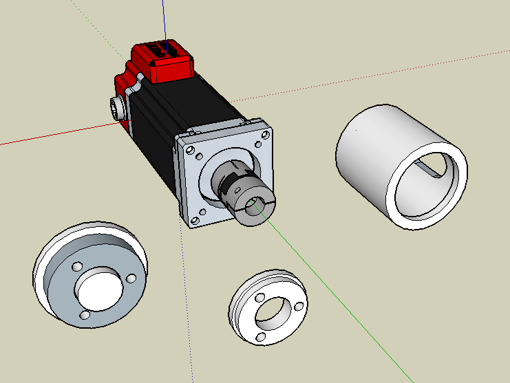
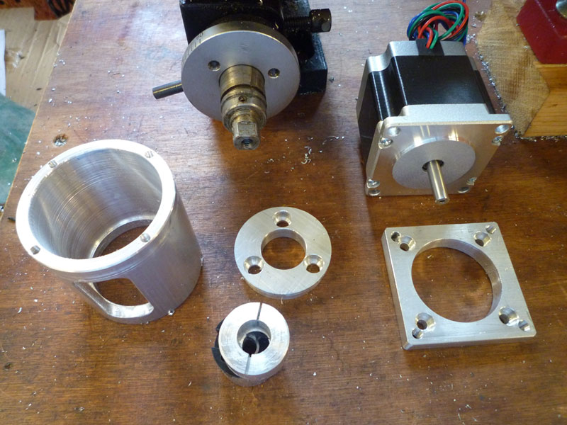
Once you remove the handle from the rotary table, you are left with a 12mm diameter keyed shaft and the 47mm diameter mounting plate that has 3 x M5 threads on a 32mm PCD.

Here is the Sketchup drawing of all the component parts for connecting a nema23 stepper motor to the rotary table, the drawing also includes the rotary table mounting plate just for completeness.
The tube was cut from a piece of 2 1/4″ (57.2mm) diameter, 1/4″ (6.35mm) wall thickness, 100mm long aluminium I bought from ebay seller forwardmetals for £7.64 ($11.46), I only needed 60mm, but this was the smallest stock size they had.
I used a Keats angle plate to hold the tube whilst I bored the internal diameter down to 48mm diameter, leaving a step at the bottom to the original 44.5mm that was 7mm long.
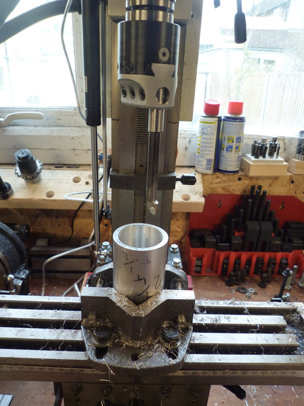
I used the Keats angle plate to secure the tube directly to the bed, as I did not have sufficient height on the Z axis to hold the tube in the vice and bore the entire height with the boring head.
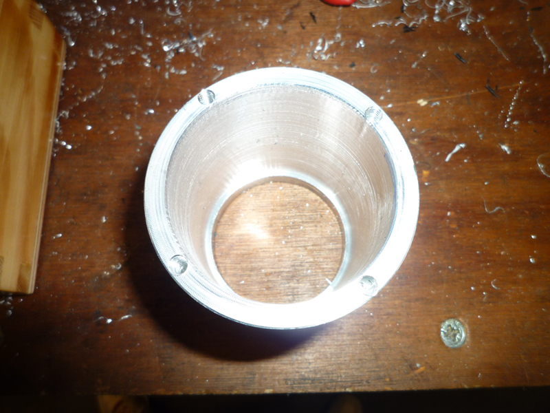
I used the DRO on the mill to drill and tap the four M4 holes for the stepper mounting plate on a 52.5mm PCD.
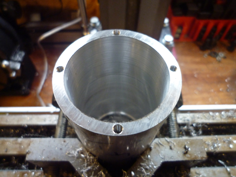
Semi finished tube – still needs a slot cutting in the side.
The plate to mount the tube to the rotary table was cut from a bar of 60x10mm aluminium, then the centre was drilled out to 19mm so it would fit on my gear cutting arbor and mounted on the lathe.
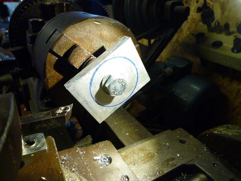
The blank was turned to be circular and of 48mm diameter,
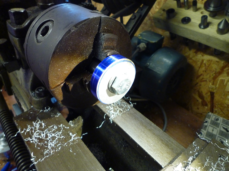
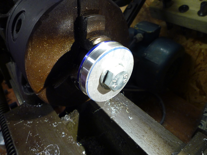
then a shoulder was cut to reduce the diameter to 44.5mm x7mm deep.
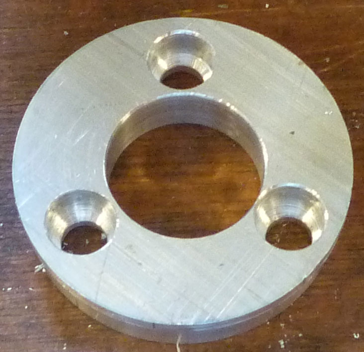
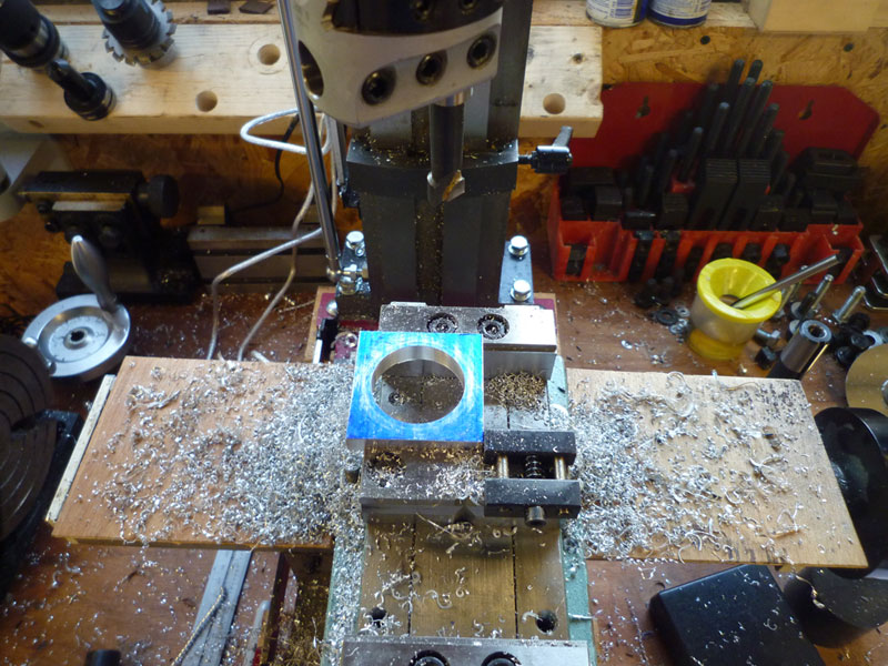
I moved the plate to the milling machine to bore the central hole to the finish size of 23mm diameter.
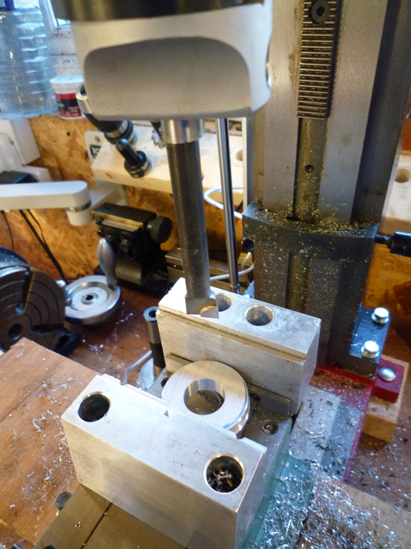
Then used the DRO to produce the 3 x mounting holes on a 32mm PCD then counterbored them with a 10mm drill, as the mounting screws are countersunk.
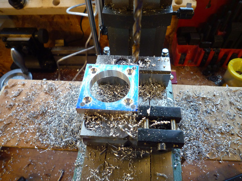
4 x M4 clearance holes drilled on a 52.5mm PCD and then countersunk
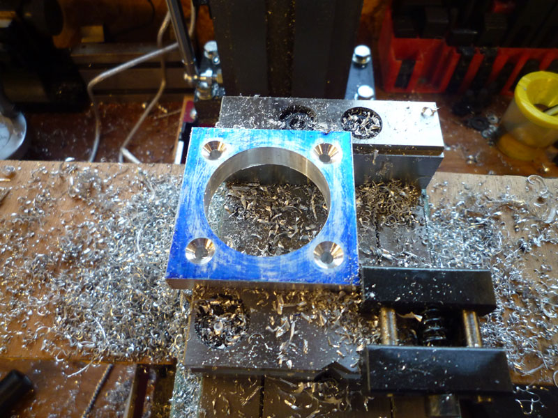
4 x M5 tapped holes on a 67.3mm PCD for mounting the stepper motor.
Here is a closeup of the slot cut in the side of the tube, this is 20x30mm and was mounted with the vice clamping against the stepper mounting plate to ensure the hole was centered on one of the sides.

Here is the completed unit with the stepper motor attached.
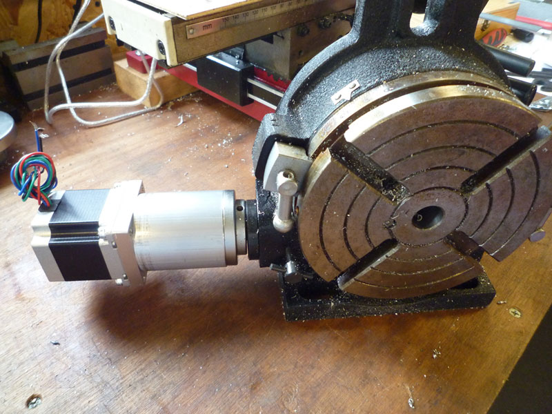
The stepper motor is a JK57HS56-2804-01, 2.8A, 12kg cm (1.26Nm, 178oz in) stepper that cost me £16.99 ($25.50) from ebay seller etang_uk.
I will make a suitable cover for the wiring on my 3D printer.