To date I have not had my Mellor lathe running under power, the motor works and I could turn the lathe by hand, however I was missing a suitable belt to connect the motor to the lay shaft.
I have plenty of ‘fan belts’ unfortunately they are all of a similar length, of around 850-950mm, and were bought for use on my various flat 4 VW engines.
Not only are these belts too long, they are also too narrow, the VW belts I have are mainly VB section belts at around 8mm at their widest part, I need an A section belt that is 13mm at its widest part.
Initially I bought an A-26 belt (660mm) for £2.99 ($4.63) inc P&P from ebay seller bearingoptions, however this turned out to be too short and would not fit.
Next I found some even cheaper belts from ebay seller bearingshop-eb, so ordered an A-30.5 (775mm) for £1.74 ($2.70) and an A-29.5 (749mm) for £1.68 ($2.60) with free P&P.
The A-30.5 was a good fit for all of the range of possible speeds between the 4 pulley cones of the lay shaft and the spindle.
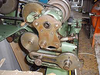
The two pulley cones are not the same size and as such the motor needs to be able to move a certain amount to allow for this, the motor will sit lower for the large end of the lay shaft cone and small end of the spindle cone compared to the opposite end of the two cones.


This is an old picture showing the lowest position of the lay shaft in the highest gear.
Unfortunately, if I attempt to use this high gear, there is not enough torque in the 1/2 HP motor to start spinning the spindle and at best it simply spins the motor pulley on the belt, at worst, it stalls and blows the fuse.
The lathe will spin in all of the other gears, and even in some of these gears with the backgear engaged to slow it down.
The backgear jumps out if some of the faster speeds are attempted and when I went looking for the adjuster screws, found them to be missing!

This image by John Mellor shows one of the adjusting screws, where it should be, below the backgear engagement lever, there should be an equivalent one beneath the other backgear mount near the chuck end of the spindle.
As such I need to buy some 1/4″x20tpi screws to install with some springs and brass bushes to press against the eccentric backshaft engagement wheels in order to try and keep the gears engaged if I ever intend to do any screw cutting.
I needed to buy some of these screws anyway for holding the change gears in place on the banjo.
I also tested out the power feed using the dog clutch on the saddle and this seems to work fine in both directions.
I have yet to try the power cross slide, or even cutting some metal with it.
One of the first projects on this lathe will be making some quick change tool posts.
I particularly like the toolpost that Mike Cox designed over at Mikesworkshop, (also shown in more detail in Model Engineers Workshop issue 158 pages 46-48), it is simple to make, the slots being milled my the lathe itself, in-situ.
Although I may yet make a variation of the Quick Change toolpost shown on the Mini-Lathe Workshop site.
Another recent purchase was a fixed steady rest from Chronos, I bought it from their ebay store chronos_ltd_engineering_supplies, as it was on special at £39.00 ($60.00) inc free P&P, as compared to their normal price of £58.80 ($91.10), also with free P&P.
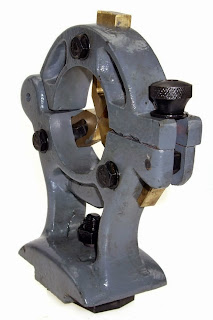
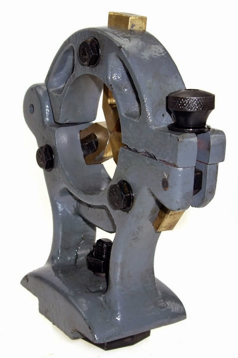
My Mellor lathe has a 3 1/2″ centre height, just the same as a Myford ML7 or Super 7 lathe, however the gap between the ways on the bed of my lathe is 50mm compared to 32.5mm on the Myford.
As a result I will either make a new bracing piece that has a slot in the middle for the base of the steady, or attach some pieces of metal to the base of the steady to make it wider.
This steady is made by Soba and I seriously doubt I could make it for less than I paid for it considering the cost of the raw castings from College Engineering Supplies are £29.88 ($46.30) + £7.80 ($12.00) P&P, if you include the phosphor bronze for the fingers, making it just £1.32 ($2.00) cheaper than the ready made unit from Chronos.
I have yet to determine the best way to make or adapt a travelling steady.
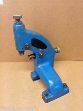
I believe the original one that would have come with the lathe attaches via 2 screws to the rear of the saddle, on top of the cross slide dovetail, and may have looked something vaguely like this Colchester travelling steady.

I may yet be able to make use of a Chronos/Soba travelling steady which is £23.76 ($36.80) inc P&P from either their ebay store, or from their main shop.


The castings from College Engineering Supplies for this item are £19.86 ($30.80) + £7.80 ($12.00) P&P, if you include the phosphor bronze for the fingers, making it £3.90 ($6.00) more expensive than the ready made unit from Chronos.
I am all for promoting machining your own items, but when the raw materials cost more than you can buy the finished product for, I fail to see the point.
The Soba steady is 3″ from centre to base, the top of the cross slide dovetail on the saddle of my lathe is 2 17/32″, where 2 1/2″ would make much more sense.
I could potentially attach a plate to the side of this steady in order to bolt it to the end of my cross slide.
Another option would be to drill some holes into the front of the cross slide and attach a steady to this.