A while ago I finally moved my Mellor lathe from where it has been sat at the back of the garage since I bought it.
Now the bed alone weighs over 200lbs (90kg) even without the saddle and tailstock, so this was not a simple task, especially without any help.
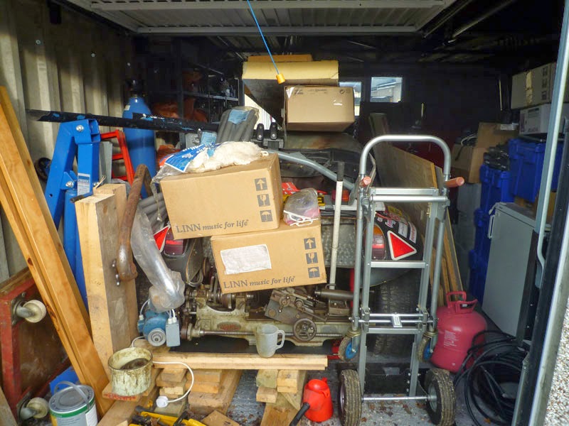
First I needed to move the lathe from the rear of the garage to the front where the workbench is situated. I decided I needed some form of skate to do this so stood the lathe on its end, so the headstock was at the top and then stood it on a small trolley jack (you can just about make it out at the bottom of the above picture – mine is yellow and black). I also have a full size 3 ton trolley jack, however this was going to be way too difficult to manoeuvre around the tight gaps in the garage.
Once I had the lathe by the workbench, the next task was to lift it onto the bench, now there was no way I was even going to attempt lifting it by hand without risking serious back injury, so I attached a large U bolt designed for truck exhaust pipe to one of the steel rafters and then used a hand crank winch clipped onto the back of the bed to lift it up to a height where I could swing the tail stock end of the bed onto the workbench.

I could then lower the lathe and push it onto the bench some more, so it would not fall off, before finally disconnecting it from the winch.
Once it was on the bench I could replace the saddle and tailstock and then secure it to the workbench and level it.
The lathe came with a couple of raising blocks (small sections of C channel rolled steel beam) which are needed if you ever want to be able to use any gears for screw cutting as the banjo hits the table (I had to remove the banjo in order to set the lathe down on the bench).
These blocks were supposed to be attached with some bolts via a plate type clamping arrangement.
This did not look very secure to me, so I drilled a 16mm hole in the C channel pieces for the bolt so it could then be attached directly to the underside of lathe bed.
Then I decided exactly where I wanted the lathe positioned, allowing space for the motor to sit behind it, and drilled some 10mm holes through the workbench so I could secure the entire assembly to the bench.

I then cut a load of thin strips of plastic to use as shims to place under the raising blocks in order to allow me to level the lathe bed.
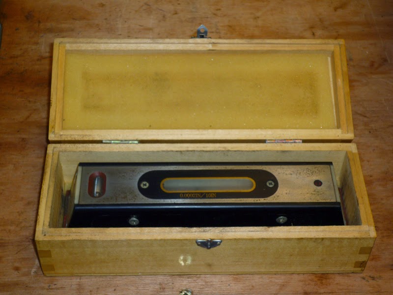
I have an engineers level I bought some time back that is accurate to 0.0002″ in 10″ (.005mm in 254mm).
I used this to ensure the bed was as level as possible, rechecking everything as I tightened the bolts securing the lathe to the workbench.
Here is the lathe in its new location with the motor also bolted into place. I need to buy a shorter and wider drive belt to go from the motor to the lay shaft as the shortest one I have just slips when the motor is running.

Front view


I would like to build up the set back to completion, so will be looking to buy some 16DP, 14.5 degree pressure angle gear cutters at some point, this is fine for the smaller gears as the blank will be relatively cheap to buy or even cast. The 127 tooth gear however, is nearly 200mm (8″) in diameter and too big to turn on my lathe.
An alternative is to use translation gears of a different pitch such as the Sherline 56DP gears which can be bought relatively cheaply (127t $18.48, 150t $36.00, 100t $15.42, 50t $9.24) and simply bore them out to the Mellor 3/4″ gear bore, this 56DP 127tooth gear is a mere 57mm (2.3″) in diameter.
I have a number of chucks for this lathe

A 7″ faceplate, a drive/catch plate, as well as 4 jaw, 3 jaw and 2 jaw chucks.
The drive/catch plate is actually a Myford item with a 1 1/8″ 12TPI UNF thread, the Mellor spindle uses a 1 1/4″ 9TPI BSF thread. If you check out the internal and external dimensions of each thread you will find that, the OD of the Myford thread is about the same as the ID of the Mellor thread, allowing me to machine off the teeth of the Myford thread before cutting a new internal thread for the Mellor.
I can also do the same for external threads with items designed for a Boxford lathe which uses a 1 1/2″ 8TPI BSF thread, this can be machined down to the OD of the Mellor 1 1/4″ 9TPI BSF thread and then a new external thread can be machined.

This model shows the three thread forms as cylinders which from the inside to the outside depict the Myford 1 1/8″ 12TPI UNF female thread, the Mellor 1 1/4″ 9TPI BSF thread and finally the Boxford 1 1/2″ 8TPI BSF thread. (UNF threads have different male and female core diameters)
Boxford and Myford threaded items are quite common on new tooling, so re-machining is a worthwhile option. I have yet to find anything else that uses the 1 1/4″ 9TPI BSF thread.