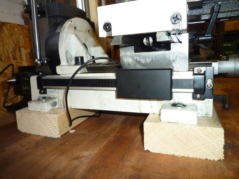
First off I cut a couple of pieces of timber to rase the Mill up so that I don’t hit my knuckles on the bench every time I try to use the Y axis, they will also provide clearance for the stepper motor once that is installed.
Suitable 10mm holes were drilled in the raising blocks and the bench and then the mill was secured with M8 coach bolts.
The bed was levelled with my engineers level, as with the lathe previously, although some much thicker shims were required on the right hand side.
These shims came with some furniture we purchased a while back, but never used the shims. This type of break-off shim is also available quite cheaply in most hardware stores.
I decided to start mounting the linear scales to the various axes on my mini mill, I checked the drill size for tapping M3 and this came out to be 2.5mm.
Having marked the first hole location and centre punched it, I proceeded to drill into the cast iron base using a battery powered hand drill taking care not to apply too much pressure that would cause the drill to snap.
Next I decided to try rigid tapping using the M3 tap in the drill chuck, unfortunately the tap was cheap rubbish and whilst it did eventually shear off, the attempt at tapping the cast iron had also stripped the cutting threads from the tap!
I had more joy on this and the other M3 holes, partly because they were all through holes, using a stainless steel M3 machine screw as a tap, backing out regularly and blowing out the dust with an air line.
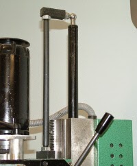
The Z axis linear slide was attached in the same way by drilling and tapping the left side of the column. I want to use the right hand side for the Z axis ballscrew.
I cut about an inch and a half off the linear slide for the X axis so that once mounted it is the same width as the table.
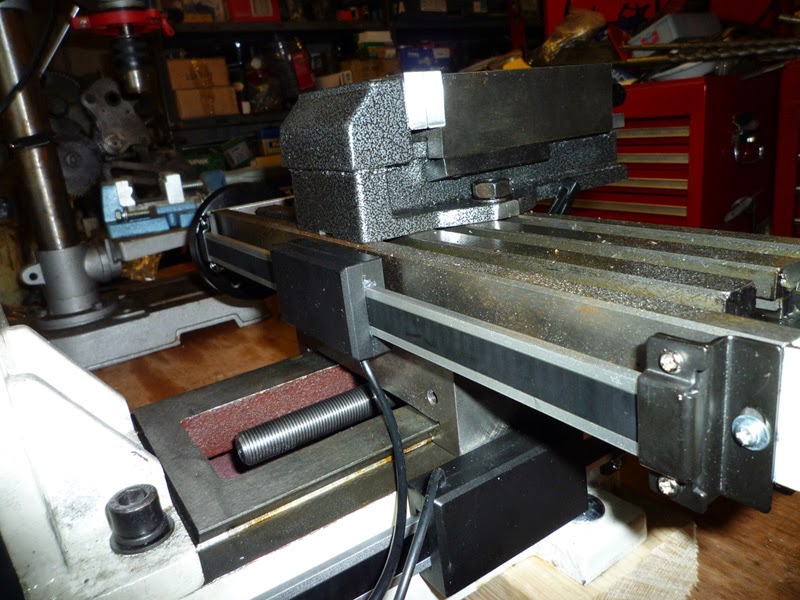
I will lose a few mm of Y travel with this linear slide in place, because the sliding part will hit the column support, but that is not the end of the world.
Many people have expressed their dislike of the Z axis torsion arm, it works reasonably well when wound up, when the head is near the table, but provides next to no support at the top end of the Z travel as there is no tension on the spring.
Grizzly apparently used to supply their version of this mill with an air spring, and LittleMachineShop sell an equivalent conversion kit, however I am not a big fan of the way it has been implemented with the gas spring sticking out of the top of the column.