This post covers the electronics side of an add-on feature for my milling machine’s rotary table.
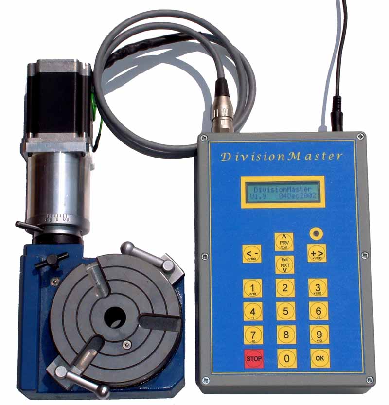
A while back I saw the Division Master product and thought this was a great idea, however I had no intention of paying the £230.00 ($345.00) price for an assembled unit or £180.00 ($270.00) for a kit of parts to build my own.
One day I stumbled upon a thread on CNCZone, where one of the members, Kwackers (Steve Ward), had built something similar back in 2007 and was willing to share the design with the other members of the forum.
I read the entire thread and also located his personal web page World of Ward, where he currently maintains all of the documentation for this project and also provides firmware downloads and even sells completed boards.
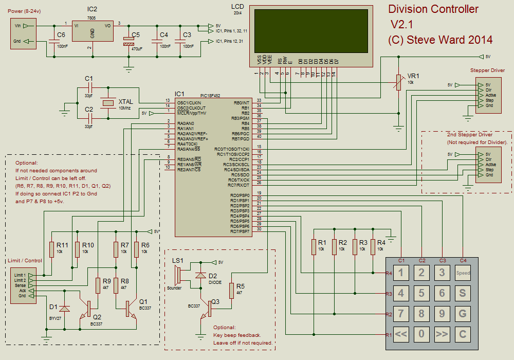
Steve provides a full schematic for the latest version of his controller that shows circuitry for various optional extras that I was not going to need.
I decided that this was a much cheaper option and started designing my own perf board variation based on the features I would require.
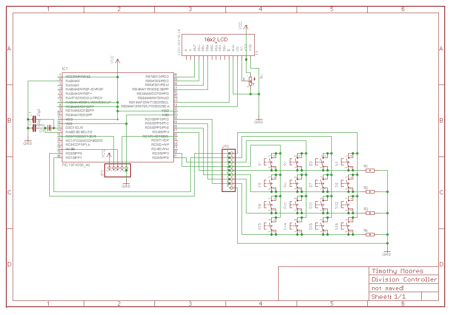
First I drew up the required circuit in Eagle
Then I drew up the perf board model in DIYLC
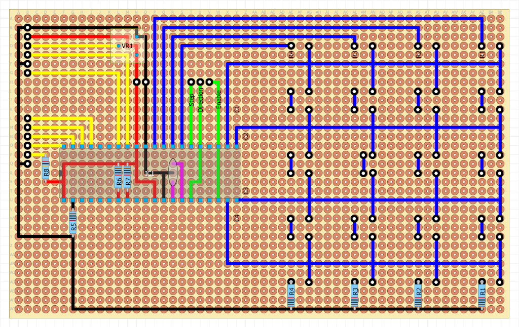
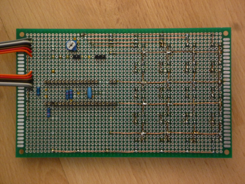
The design makes use of a through soldered double sided board that is 54×33 holes (90x150mm).
The board was bought from ebay seller eachdesk at a cost of £2.78 ($4.17) for 2 boards or £1.39 (2.085) each.
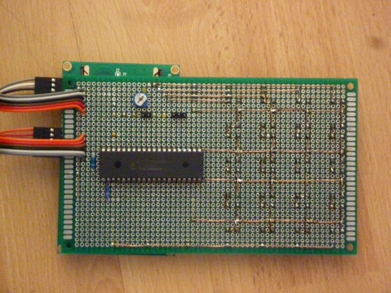
The design calls for a PIC18F452 microcontroller chip, which was one I did not already have, so I placed a sample order with Microchip and about a week later 3 units turned up for free.
The screen was ordered from ebay seller 144mph for a cost of £5.73 ($8.60) for 2 or £2.86 ($4.30) each.
The 12mm tactile buttons came from ebay seller fzeroinestore for a cost of £1.39 ($2.08) for 50 or £0.03 ($0.04) each.
The 12mm button caps came from ebay seller deal24hours_ca for a cost of £1.99 ($3.00) for 140 or £0.01 ($0.02) each.
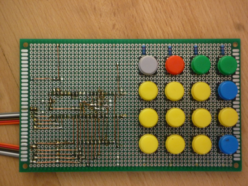
The reason for the double sided board is so that I can place the buttons on one side and have all of the components on the rear, many of the connections make use of the holes to allow the wire to change from one side of the board to the other.
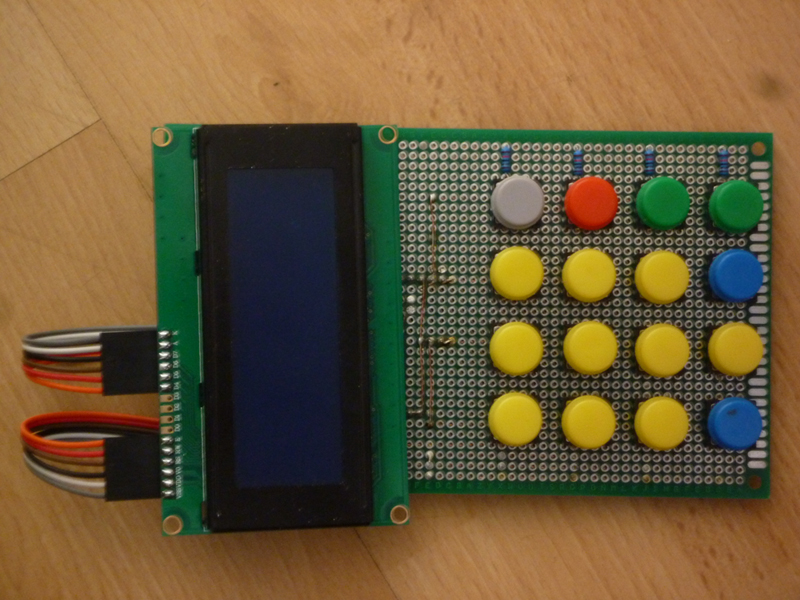
To allow the screen to be removable I decided that the simplest option was to make use of 2 single row 6 pin Dupont connectors and 90 degree pin headers on the LCD itself.
I skipped all of the optional circuitry as well as the voltage regulator, as I would be using an off-board DC-DC switch mode buck converter to drop the 19V laptop power supply to the required 5V for the controller.
This buck converter would also be supplying the 5V supply to the PMinMO stepper driver.
Component side (rear) of finished board
Button side (front) of finished board
Rear with PIC18F452 microcontroller installed
Front with LCD connected
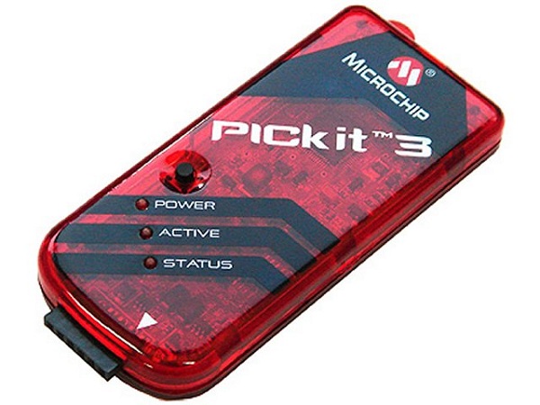
The firmware was uploaded using a clone PICkit2 programmer I bought from ebay seller alice1101983 for £6.23 ($9.35)
and a ZIF adapter from ebay seller lakeyx101 for £1.57 ($2.36)
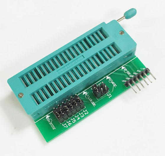
These two items cannot really be factored into the cost of the division controller as I can use them on any future PIC based projects.
The case for this project will be 3D printed and that will be covered in a separate post on my 3D printer blog.
In total this project cost me about £5.00 – quite a saving over the £180.00 price of a Division Master kit.