This is an update and move of a post that was originally posted on my PCB CNC Machine Blog.
The PMinMO website has unfortunately now shut down due to the owner suffering from health issues, although it can still be accessed via Wayback machine.
The PMinMO Toshiba 6560AHQ board design was a collaboration with HWML.com.
The Eagle and gerber files to make these boards were provided on the PMinMO website.
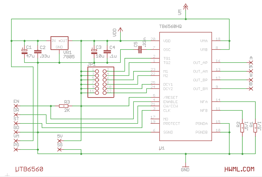
Schematic
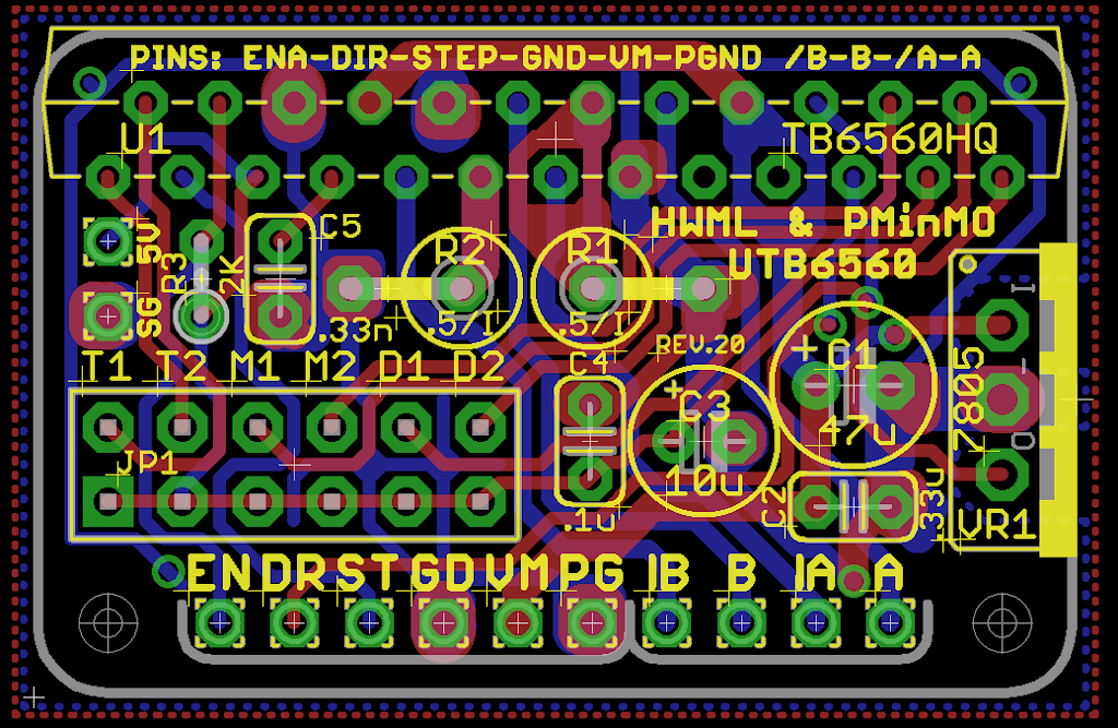
Board layout
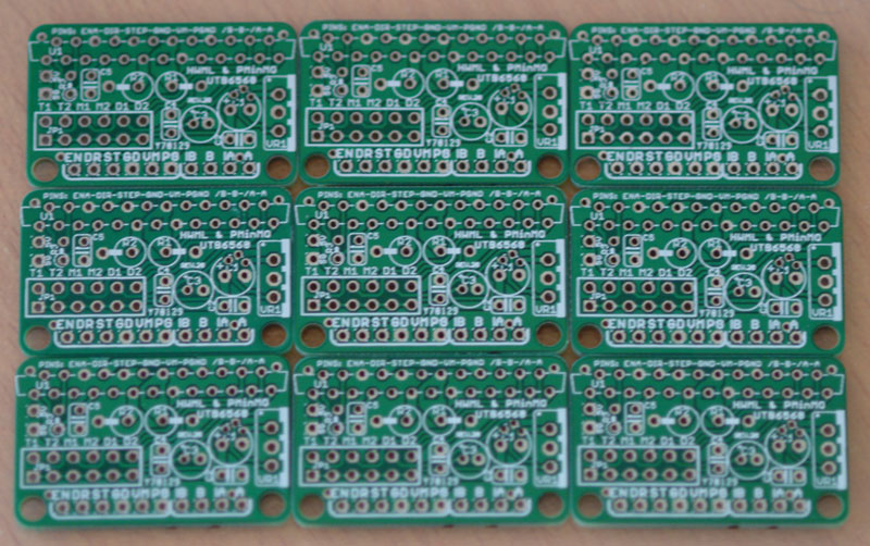
I sent the gerber files to ITead Studio, ($9.99 for 10) who had a few issues processing my order, so I ended up with 9 rather than 10, but still a bargain at $1.11 or £0.69 each.
Here are all the parts ready to be stuffed onto the board:
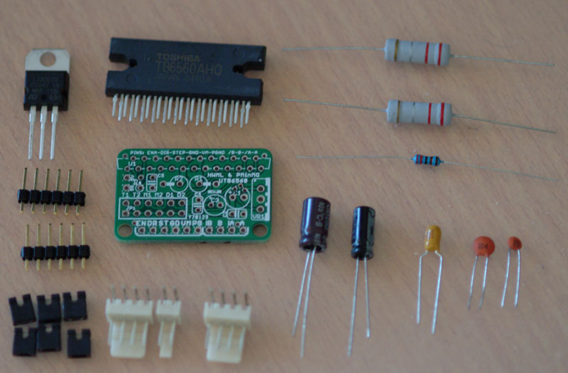
The resistors I am using are 0.22 Ohms, so good for up to 2.27A per motor.
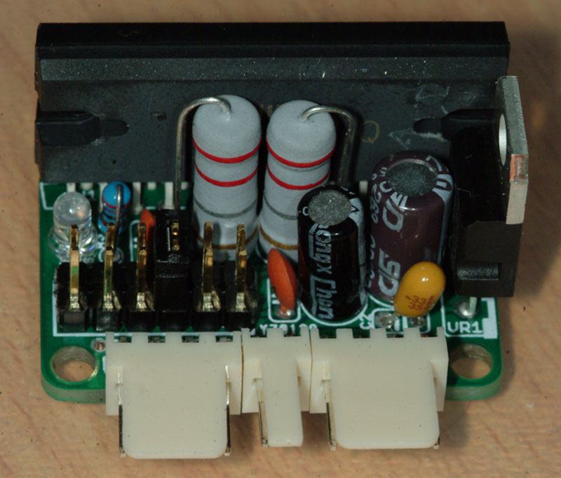
Total cost of the board and components £4.25 for a board capable of up to 36V and 2.27A.
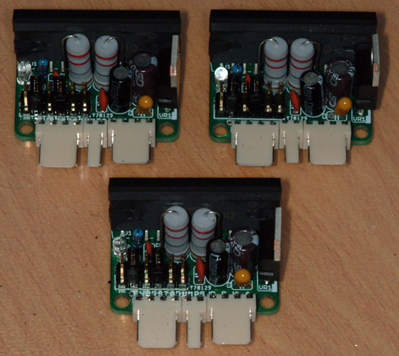
3 drivers ready for testing. I have some heat sinks on order for the voltage regulators (£1.13 for 10), just need to find a suitable heat sink for the Toshiba chips.
The initial tests did not go well.
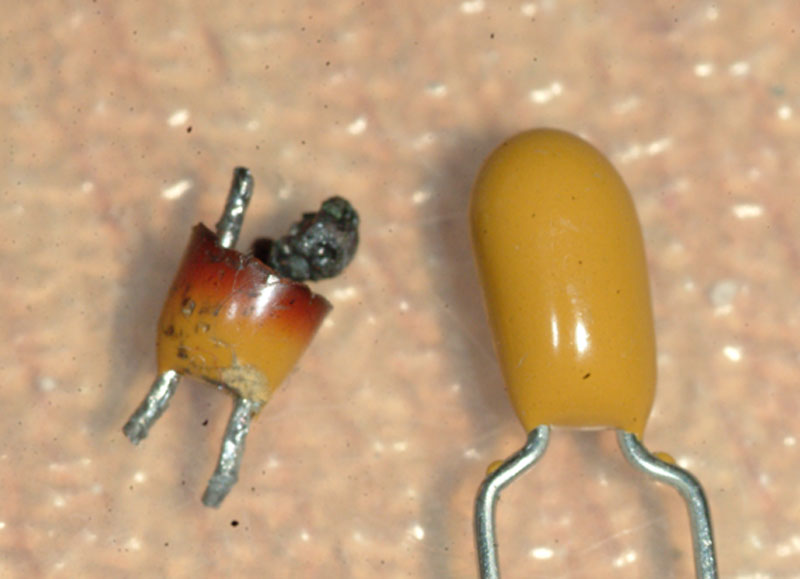
Fried the LED in about the first 2 seconds, then fried one of the capacitors associated with the voltage regulator – nice plume of smoke from that one, did not smell too good either, very acrid, probably not good to breathe in.
Spot the difference :o)
Open the window to allow a through draught to clear the smoke and have a think about what went wrong.
Carried out some more continuity testing and all seems fine, so not sure why the capacitor went up, unless maybe the LED fused closed across the ground and 5V lines.
Replaced the components and tried again, but at a lower starting voltage, 5V and all is well, 10V and the LED goes up in smoke again, not having much luck here, definitely 5V coming out of the voltage regulator.
Maybe too much current going through the LED, after all it is not protected by anything, just connected across a 5V and ground pair of pins.
Removed the LED and tried again – all fine, still fine at 19V, motor holds still, but is held firmer at full current (removed the current limiting T2 jumper).
Removed the LEDs from the other boards as well just so that they don’t go up in smoke too.
Next to test it with some step and direction commands.