I have been looking at ways of using the PWM output of GRBL to control a brushless RC motor via an ESC.
Now there is a commercial option available from Logicnc, but I object to paying $34.99 for something that can potentially be made for pennies.
I came across a post by Kretov on the CNCZone covering this very topic.
He had posted a schematic and hex files, along with source code to implement this on a PIC12F629 (DIP 8) chip.
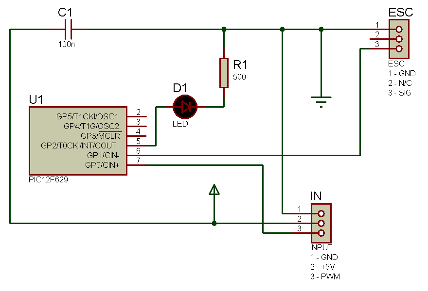
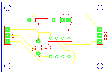
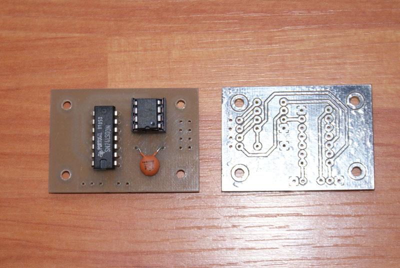
He even posted a suitable PCB layout.
I also came across a similar post by Tweakie on the OpenBuilds website which discusses exactly the same type of process, again with hex files for use on a PIC micro-controller.
His implementation uses NAND gates to provide buffering and a clean square wave, and is further enhanced with the provision for manual control via a potentiometer.
Now I have nothing against PIC chips, especially as Microchip are willing to give away free samples of their micro controllers, which is more than can be said for Atmel, I just have yet to become familiar with their associated programming environment.
As such I decided to attempt to port the code written by Kretov to a suitable AVR chip.
My first choice, given the limited number of pins required (3), was to use an ATtiny25/45/85 (DIP8) chip, unfortunately, this has 2 x 8 bit timers, and this project calls for 1 x 8 bit and 1 x 16 bit timer or ideally 2 x 16 bit timers.
So the next size up is the ATtiny24/44/84 (DIP 16) family, where it does indeed have the required timers.
Unfortunately, /16 is not an available prescaler for the 8 bit timer and so I had to make use of /64 instead.
This is still a work in progress and has yet to be tested, but I believe I now have a useable set of code:
// 8 bit Timer 0 and /64 prescaler used for input, 125 ticks = 1ms
// 16 bit Timer 1 and /8 prescaler used for output, 1000 ticks = 1ms
// PWM input connected to PA0 (Pin 13)
// ESC output connected to PB0 (Pin 2)
uint16_t MIN_WIDTH = 125; // 8MHz /8 = 1000 clock ticks = 1ms
uint16_t MAX_LENGTH = 125; // 8MHz /8 = 1000 clock ticks = 1ms
uint16_t OUT_PERIOD = 1000; // 8MHz /16 = 16000 clock ticks = 20ms
uint16_t MAX_WIDTH = MIN_WIDTH + MAX_LENGTH; // 2ms
uint16_t InPeriod = 0;
volatile uint16_t Pulse = MIN_WIDTH; // 1ms
void setup(void)
{
// Setup Interrupts
GIMSK |= (1 << PCIE1); // Enable Interrupts on Pin Change
PCMSK0 |= (1 << PCINT0); // Generate Interrupts on PA0 (Pin 13)
sei(); // enable interrupts
// Setup Timer 0
TCCR0B |= (1 << CS00) | (1 << CS01); // /64 prescaler on Timer 0
TCNT0 = 0; // Initialise counter for Timer 0
// Setup Timer 1
TCCR1B |= (1 << CS11); // /8 prescaler on timer 1
TIFR1 |= (1 << ICF1); // clear interrupt-flag
TIMSK1 |= (1 << ICIE1); // enable Timer1 input capture interrupt
TCNT1 = 0; // Initialise counter for Timer 1
// Setup Ports
DDRB |= (1 << DDB0); // enable port B0 (pin 2) for output
CalcOutput(); // arm ESC
}
void CalcOutput() { // calculate Timer 1 overflow based on Pulse
uint16_t i = 0xFFFF;
if (PINB & (1 << PINB0)) { // last input low
i -= OUT_PERIOD – Pulse; //
} else { // last input high
i -= Pulse;
}
TCNT1 = i;
}
ISR (PCINT0_vect) {
if (TOV1 == 0b1) { // Timer 1 wrapped
PORTB ^= (1 << 0); // Flip Port B0
CalcOutput();
TIFR1 &= ~(1 << TOV1); // Reset Timer 1 Overflow flag
}
if (PCINT0 == 0b1) { // Input pin data changed
if (PINA & (1 << PINA0)) { // last input high
InPeriod = TCNT1; // Period = timer count
TCNT1 = 0; // Reset Timer Count
} else {
if (InPeriod > 0) { // don’t calculate on first run through
Pulse = MAX_WIDTH + MAX_LENGTH * TCNT0 / InPeriod; // re-scale output
if (Pulse > MAX_WIDTH) Pulse = MAX_WIDTH;
if (Pulse < MIN_WIDTH) Pulse = MIN_WIDTH;
}
}
}
if (TOV0 == 0b1) { // Timer 0 wrapped – no pulses detected
if (PINA & (1 << PINA0)) { // last input high
Pulse = MAX_WIDTH; // max pulse
} else { // last input low
Pulse = MIN_WIDTH; // min pulse
}
InPeriod = 0; // Reset Period
TIFR0 &= ~(1 << TOV0); // Reset Timer 0 overflow flag
}
}
void loop() { // Do Nothing – all handled in ISR
}