I have since had some more thoughts on this subject and after counting the connections again, decided that it could be implemented with an ATtiny85/45/25 DIP 8 chip.
After downloading the DRO_2_2 source code from Yuriy’s website and compiling it up noticed that it will fit on an ATtiny85 or 45, but not on a 25 because at 2294 bytes it requires slightly more than the 2048 bytes of memory available on the 25 chip.
If I use TinyDebugSerial, this gives me TX only, however this is all I need and it still works with the standard Arduino Serial.print, etc functions – the TX connection on the ATtiny85/45/25 chip is on pin PB3 or Digital 3.
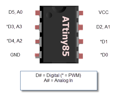
Clock – digital pin 0
X Data – digital pin 1
Y Data – digital pin 2
Z Data – digital pin 4
After all only 7 pins are being used anyway (inlcuding GND and VCC), so a full blown Arduino or dip 28 atmega328p chip is not required.
The pull-up resistors are not actually required for any of the Arduino based options as there are internal pull-ups that can be used (pinmode(pin, INPUT_PULLUP)), and if run at 3V, then the voltage divider is not required either.
The ATtiny85/45/25 chips can be run at 8MHz using their internal clocks at 5V or 3V.
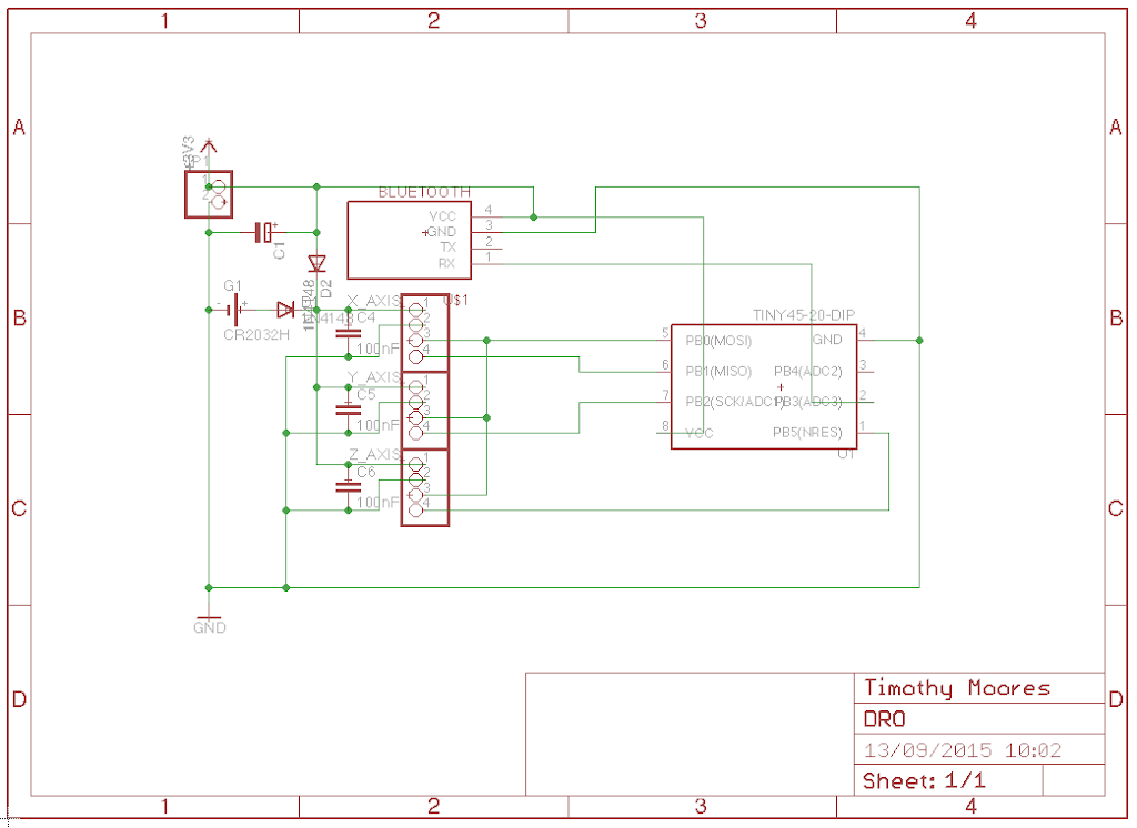
I adjusted the schematic
Circuit board
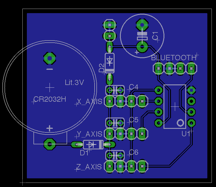
You will note that I have re-arranged the various USB cable pins in order to simplify the board layout, this also means that I can use any shielded cable that happens to have a mini USB connection at one end and replace the other end with a 4 pin Dupont connector.
I ultimately decided to build it with female USB connectors so I don’t have to cut the ends off the USB connectors, which made for slightly more complex wiring.
I had to move the Z axis pin from pin 1 to pin 3 because otherwise I would need to disable the reset function and lose the ability to easily program the chip, but this was no big deal.
Ensure you upload a bootloader to these chips before programming, or the fuses do not set, you may also need to slow down the communication to using JP3 on a USBASP programmer when burning a brand new chip.
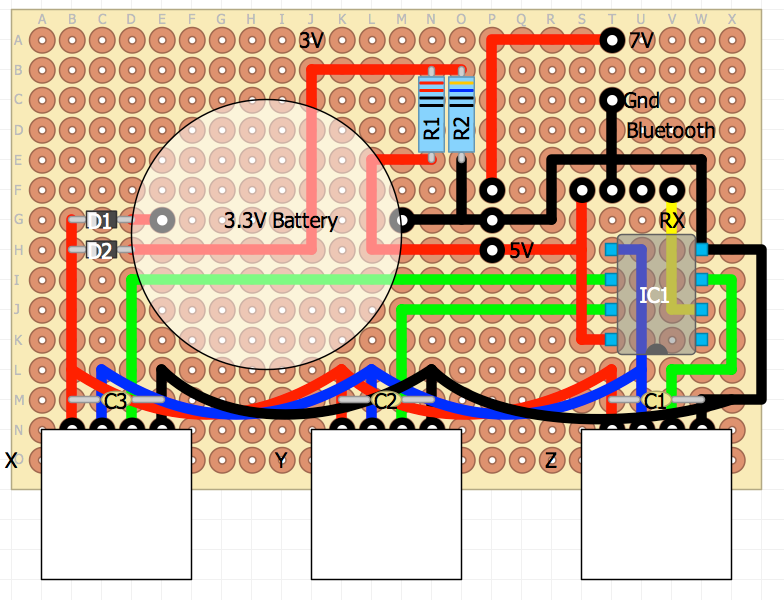
The 7V supply is from a telephone power supply, this is then dropped to a regulated 5V by a cheap switch mode Buck converter (£8.75 ($13.50) for 10 from ebay seller chesk_2013).
I then also drop the 5V to 3.1V with a voltage divider for powering the scales using a 220 Ohm and 360 Ohm resistor.
I could have dropped the 7V to 5V using a voltage divider as well, but was unsure how well regulated the 7V supply was.
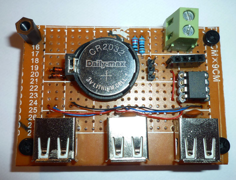
Here is the completed circuit board
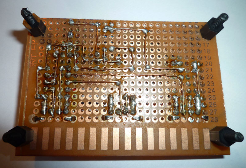
Rear view
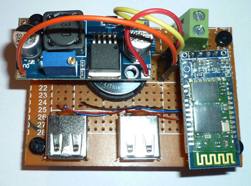
and with the voltage regulator and bluetooth modules installed.
Total cost for the parts is £2.50 for the bluetooth module, £0.87 for the regulator, £0.10 for the 2032 holder, £0.60 for the USB connectors, £0.95 for the ATtiny45 chip, £0.10 for the perf board and a few pennies for the diodes, pins and capacitors, so about £5.00 ($7.50) in total. The 2032 cell came with the scales, so I am not including this in the total, although they are only about £0.20 each anyway.