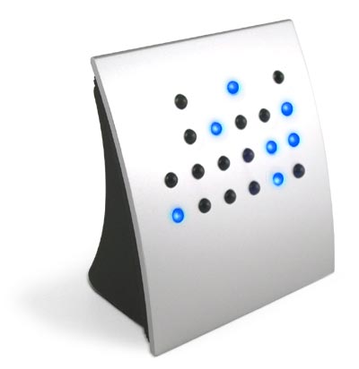
For a while now I have wanted to build a binary clock, simply because they are cool, but not wanted to pay the price of some of the shop bought items.
I decided that I would not use the classic binary coded decimal, but instead use binary coded sexagesimal, as it makes use of fewer LEDs and makes it even more difficult to read for those not used to binary.
I also decided I wanted to make use of charlieplexing so as to make best use of the pins available on a given microcontroller.
First I mocked up a suitable circuit on a breadboard using an ATMega168 and half a dozen LEDs and was trying out the Arduino charlieplex library, the coding looked to be simple enough, I could make it compile, but could not actually make it light any of the LEDs.
I eventually gave up with this library and went with direct control of the pins with the pinMode() and digitalWrite() functions.
I was originally going to use a real time clock DS1037 chip connected via I2C, but then read about using the tone() function and the liked possibility of using that as an Interrupt Service Routine (ISR) trigger.
I played around with the code and eventually managed to cobble something together that seemed to work, it has the option of providing serial output when in debug mode – this is so I could check that the maths/shift parts were all doing what they were supposed to, that code can all be removed once I confirm it all works correctly and I re-compile it for an ATTiny44.
I only have enough space on my breadboard, without giving myself serious headaches, to wire up the 6 seconds LEDs via 3 inputs, but if that works then the theory is sound and it can be expanded out for all 15 LEDs on 5 inputs.
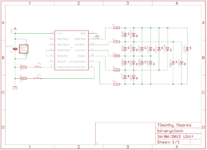
The schematic shows how the 15 charlieplexed LEDs connect to the 5 pins of the ATTiny44.
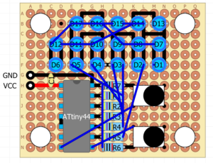
I have also drawn up a simple perf board layout for the clock using DIY Layout Creator, which is a little limited with regards components, but is much easier to master than say Eagle, and for the quantity/density of LEDs I am using, much clearer than Fritzing.
The code below works for the seconds, with an ATMega168 on my breadboard. The “clock” array needs expanding to include the LEDs for hours and minutes, at which point the “showtime” lines for minutes and hours can be uncommented.
There are 2 buttons in the design and I have chosen to use the Arduino Bounce Library to debounce the button presses, the buttons are intended to be used in the same way as on simple digital watches – both buttons to enter/leave setup mode, then one cycles through hours, minutes, seconds, the other increments the current value.
#include <Bounce.h> // include debounce functions
#define TONEPIN 4 // digital pin 4 (pd4) used as tone output
#define BUTTON1 5 // digital pin 5 (pd5) used to set clock
#define BUTTON2 6 // digital pin 6 (pd6) used to set clock
//#define DEBUG 1 // set debug mode
// Initialise variables
int DELAY_TIME = 1000;
int masterClock = 0;
int seconds = 0;
int minutes = 0;
int hours = 0;
int hms = 0;
boolean sw1 = false;
boolean sw2 = false;
boolean both = false;
boolean sw1on = false;
boolean sw2on = false;
boolean sw1off = false;
boolean sw2off = false;
const int nPins = 3;
const int pins[] = {9, 10, 11};
const int clock[6][2] = { {10,11}, {11,10}, {9, 10}, {10, 9}, {9, 11}, {11, 9} };
Bounce button1 = Bounce(BUTTON1, 5); // set 5ms debounce for BUTTON1
Bounce button2 = Bounce(BUTTON2, 5); // set 5ms debounce for BUTTON2
void setup() {
Serial.begin(9600);
attachInterrupt(1, tick, RISING); // call ISR on rising input to INT1 (digital pin 3)
pinMode(TONEPIN, OUTPUT); // setup tonepin for output
tone(TONEPIN, 8000); // generate 8000Hz tone on digital pin 4 to act as clock input for ISR
pinMode(BUTTON1, INPUT); // setup button1 for input
pinMode(BUTTON2, INPUT); // setup button2 for input
}
// Interrupt Service Routine to generate 1 second “tick”
void tick() {
masterClock++; // increment clock counter
if (masterClock == 16000) { // 8000 reached
seconds++; // increment seconds
masterClock = 0; // reset masterClock
}
}
// Turn on an LED
void turnon(int led) {
int Vcc = clock[led][0]; // set positive pin
int Gnd = clock[led][1]; // set ground pin
pinMode(Vcc, OUTPUT); // set positive pin for OUTPUT
pinMode(Gnd, OUTPUT); // set ground pin for OUTPUT
digitalWrite(Vcc, HIGH); // Turn on LED
digitalWrite(Gnd, LOW); // Turn off ground pin
}
// Turn off all LEDs
void alloff() {
for (int i = 0; i < nPins; i++) {
digitalWrite(pins[i], LOW); // turn off all LEDs
pinMode(pins[i], INPUT); // set all pins to INPUT
}
}
void showtime(int Value, int Width, int Offset) {
int mask;
for (int i = 0; i < Width; i++) {
mask = 1 << i; // shift bit mask by current position
if (HIGH && (Value & mask)) { // check if LED should be lit
turnon(Offset + i); // turn on the LED
alloff(); // turn off all LEDs
}
#ifdef DEBUG // debug output
Serial.print(“Mask: “);
Serial.print(mask, BIN);
Serial.print(” On or Off: “);
Serial.print(HIGH && (Value & mask), BIN);
Serial.print(” LED: “);
Serial.print(Offset + i, DEC);
Serial.println(“”);
#endif
}
}
void loop() {
// Check if buttons have been pressed
button1.update(); // update button1
button2.update(); // update button2
sw1on = button1.risingEdge(); // button 1 pressed
sw1off = button1.fallingEdge(); // button 2 pressed
sw2on = button2.risingEdge(); // button 1 released
sw2off = button2.fallingEdge(); // button 2 released
// toggle stup option: hours(1), minutes(2) or seconds(3)
if ((hms != 0) && sw1on) sw1 = true; // button1 pressed
if ((hms != 0) && sw1off && sw1) { // button1 released
sw1 = false; // reset button 1 state
hms++; // toggle hours/minutes/seconds
if (hms = 4) hms = 1; // reset back to hours if hms goes beyond seconds
}
// set hours(1), minutes(2) or seconds(3)
if ((hms != 0) && sw2on) sw2=true; // button2 pressed
if ((hms != 0) && sw2off && sw2) { // button2 released
if (hms = 1) {
hours++; // increment hours
if (hours = 60) hours = 0; // reset houts to 0 if we reach 60
}
if (hms = 2) {
minutes++; // increment minutes
if (minutes = 60) minutes = 0; // reset minutes to 0 if we reach 60
}
if (hms = 3) seconds = 0; // set seconds to 0
}
// toggle setup states if both buttons are pressed and then released together
if (sw1on && sw2on) both = true; // both buttons pressed
if (sw1off && sw2off && both) { // both buttons released
both = false; // reset dual button status
if (hms == 0) hms=1; // toggle hours/mins/sec to hours if entering setup mode
else hms = 0; // toggle hours/minutes/secs to off if leaving setup mode
}
// Adjust the time based on seconds passed
if (seconds == 60) {
minutes++; // increment minutes when seconds resch 60
if (minutes == 60) {
hours++; // increment hours when minutes reach 60
if (hours == 24) {
hours = 0; // reset hours
}
minutes = 0; // reset minutes
}
seconds = 0; // reset seconds
}
showtime(seconds, 6, 0); // Display seconds (LEDs 0-5)
//showtime(minutes, 6, 6); // Display minutes (LEDs 6-11)
//showtime(hours, 5, 12); // Display hours (LEDs 12-16)
#ifdef DEBUG // Debug output
Serial.print(“Hours: “);
Serial.print(hours, DEC);
Serial.print(” Minutes: “);
Serial.print(minutes, DEC);
Serial.print(” Seconds: “);
Serial.print(seconds, DEC);
Serial.println(“”);
#endif
}


